Altera DDR SDRAM High-Performance Controllers and ALTMEMPHY IP User Manual
Page 77
Chapter 5: Functional Description—ALTMEMPHY
5–31
ALTMEMPHY Signals
June 2011
Altera Corporation
External Memory Interface Handbook Volume 3
Section I. DDR and DDR2 SDRAM Controllers with ALTMEMPHY IP User Guide
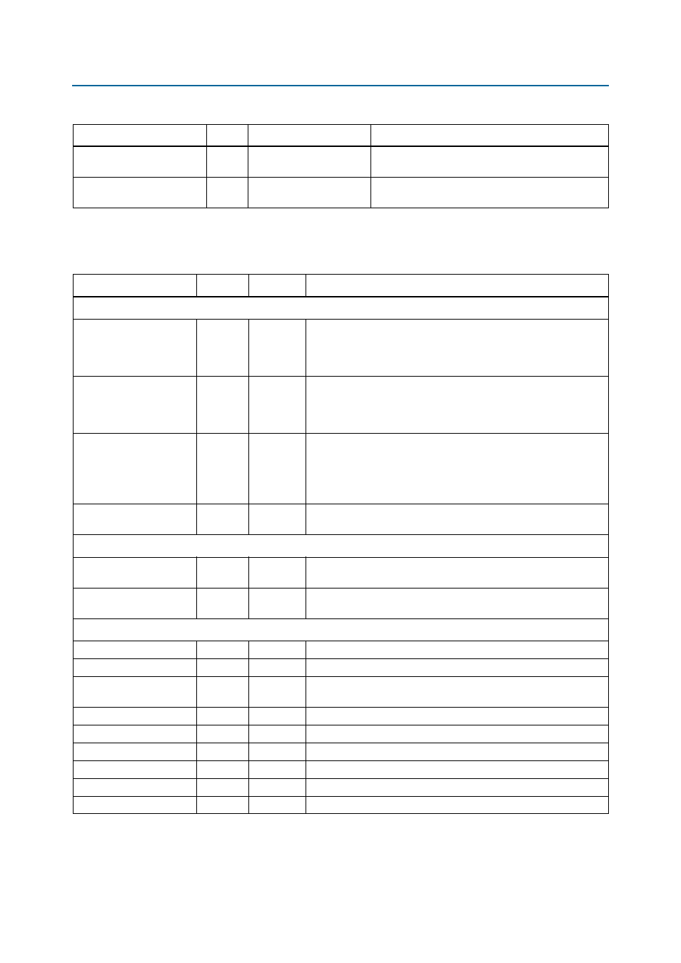
ctl_cal_req
Input
1
When asserted, a new calibration sequence is started.
Currently not supported.
ctl_cal_byte_lane_
sel_n
Input
MEM_IF_DQS_WIDTH
×
MEM_CS_WIDTH
Indicates which DQS groups should be calibrated.
Note to
Table 5–5
:
(1) Refer to
Table 5–8
for parameter descriptions.
Table 5–6. AFI Signals (Part 4 of 4)
Signal Name
Type
Width
(1)
Description
Table 5–7. Other Interface Signals (Part 1 of 3)
Signal Name
Type
Width
Description
External DLL Signals
dqs_delay_ctrl_expor
t
Output
DQS_DELA
Y_CTL_WI
DTH
Allows sharing DLL in this ALTMEMPHY instance with another
ALTMEMPHY instance. Connect the dqs_delay_ctrl_export port
on the ALTMEMPHY instance with a DLL to the
dqs_delay_ctrl_import
port on the other ALTMEMPHY instance.
dqs_delay_ctrl_impor
t
Input
DQS_DELA
Y_CTL_WI
DTH
Allows the use of DLL in another ALTMEMPHY instance in this
ALTMEMPHY instance. Connect the dqs_delay_ctrl_export port
on the ALTMEMPHY instance with a DLL to the
dqs_delay_ctrl_import
port on the other ALTMEMPHY instance.
dqs_offset_delay_ctr
l_ width
Input
DQS_DELA
Y_CTL_WI
DTH
Connects to the DQS delay logic when dll_import_export is set
to IMPORT. Only connect if you are using a DLL offset, which can
otherwise be tied to zero. If you are using a DLL offset, connect this
input to the offset_ctrl_out output of the dll_offset_ctrl
block.
dll_reference_ clk
Output
1
Reference clock to feed to an externally instantiated DLL. This clock
is typically from one of the PHY PLL outputs.
User-Mode Calibration OCT Control Signals
oct_ctl_rs_value
Input
14
OCT RS value port for use with ALT_OCT megafunction if you want
to use OCT with user-mode calibration.
oct_ctl_rt_value
Input
14
OCT RT value port for use with ALT_OCT megafunction if you want to
use OCT with user-mode calibration.
Debug Interface Signals
(Note 1)
,
(Note 2)
dbg_clk
Input
1
Debug interface clock.
dbg_reset_n
Input
1
Debug interface reset.
dbg_addr
Input
DBG_A_WI
DTH
Address input.
dgb_wr
Input
1
Write request.
dbg_rd
Input
1
Read request.
dbg_cs
Input
1
Chip select.
dbg_wr_data
Input
32
Debug interface write data.
dbg_rd_data
Output
32
Debug interface read data.
dbg_waitrequest
Output
1
Wait signal.