J4 and j5 – serial port connector pin-outs – Rockwell Automation 1398-DDM-xxx USE MNL/ULTRA 200 DIG.SERVO.DR User Manual
Page 99
Publication 1398-5.0 – October 1998
Interfaces
6-35
●
Even, odd, and no parity generation/checking are supported. No
parity is the factory default setting.
●
The maximum number of ULTRA 200 Series drives allowable on
an RS-485 bus is 32.
●
The maximum length of an RS-232 cable is 15 meters (50 feet).
●
The maximum length of an RS-485 cable is 1220 meters (4000
feet) with 0.20 mm
2
(24 AWG) wire.
Allen-Bradley cables are available in various lengths for connecting to
the serial port of an ULTRA 200 Series drive and a control unit, such
as a PC. “Options and Accessories” on page A-1 lists the cables, and
the male and female connectors for the cables.
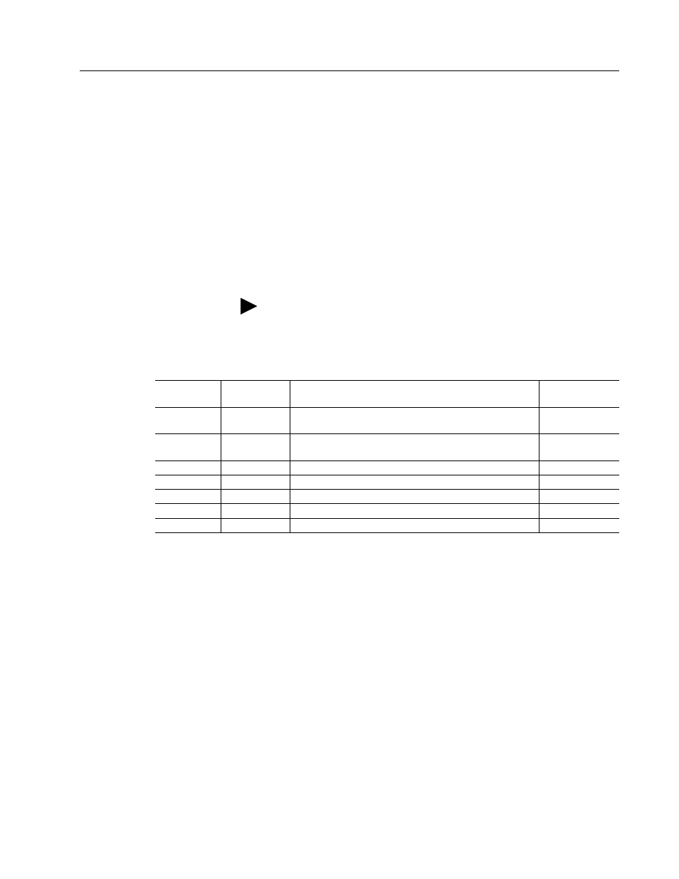
The following table lists the pin-outs for J4 and J5.
Note: The shell of the connector is grounded to the chassis for shield
termination.
Table 6.24:
J4 and J5 – Serial Port Connector Pin-Outs
Signal Pin
Number
Description
Internal
Connections
RCV (+)
RCV (-)
J4 - 1 (+)
J4 - 7 (-)
RS-485 differential receiver input (to drive)
J5 - 1 (+)
J5 - 7 (-)
XMT (+)
XMT (-)
J4 - 4 (+)
J4 - 8 (-)
RS-485 differential transmitter output (from drive)
J5 - 4 (+)
J5 - 8 (-)
COM
J4 - 5
Common serial port interface
J5 - 5
J4 - 6
Reserved
a
J5 - 6
RCV
J4 - 2
RS-232 receiver input (to drive)
J5 - 2
XMT
J4 - 3
RS-232 transmitter output (from drive)
J5 - 3
J4 - 9
Reserved
1
J5 - 9
a. Do not connect any device to J4-6, J5-6, J4-9 or J5-9, except an Allen-Bradley TouchPad.