Encoder sequencing, Required back-emf and hall signal phasing, Figure d.2. mot – Rockwell Automation 1398-DDM-xxx USE MNL/ULTRA 200 DIG.SERVO.DR User Manual
Page 268: Figure d.2, Nd figure d.2, To figure d.2
Publication 1398-5.0 – October 1998
D-4
Creating Custom Motor Files
Many motor manufacturers include drawings in their data sheets that
identify the phasing of the back-EMF and Hall feedback signals, or an
application engineer may have access to an internal document listing
the information. As a last resort, the motor can be rotated in the lab to
check the phasing.
If the phasing is not correct, the respective leads must be physically
swapped to correct the sequencing. A custom motor file cannot be
created until the sequencing is correct because the offset of the Hall
signals from the Allen-Bradley standard must be defined, and
swapping wires affects the offset value.
Encoder Sequencing
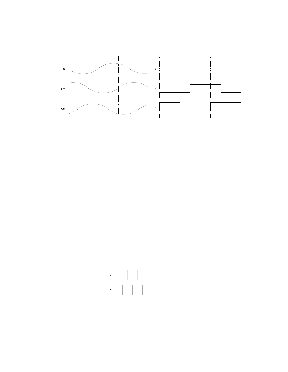
Separate from the phasing of the commutation and motor power
signals, the encoder A quad B signals must sequence properly. The A
channel must lead the B channel for CW motion when viewed looking
at the motor shaft from the load. Figure D.3 depicts this encoder
signal sequencing. If the encoder phasing is not as shown in
Figure D.3, the encoder leads must be swapped.
Figure D.2
Required Back-EMF and Hall Signal Phasing
for Clockwise Rotation
Intro
Intro
Intro
(a) Required Back-EMF Phasing
(b) Required Hall Feedback Phasing
Figure D.3
Phasing of the Encoder Signals for Clockwise Rotation
Intro