Motor phasing, Back-emf and hall signals, Creating custom motor files d - 3 – Rockwell Automation 1398-DDM-xxx USE MNL/ULTRA 200 DIG.SERVO.DR User Manual
Page 267: Figure d.1 allen-bradley motor naming convention, Motor part number
Publication 1398-5.0 – October 1998
Creating Custom Motor Files
D-3
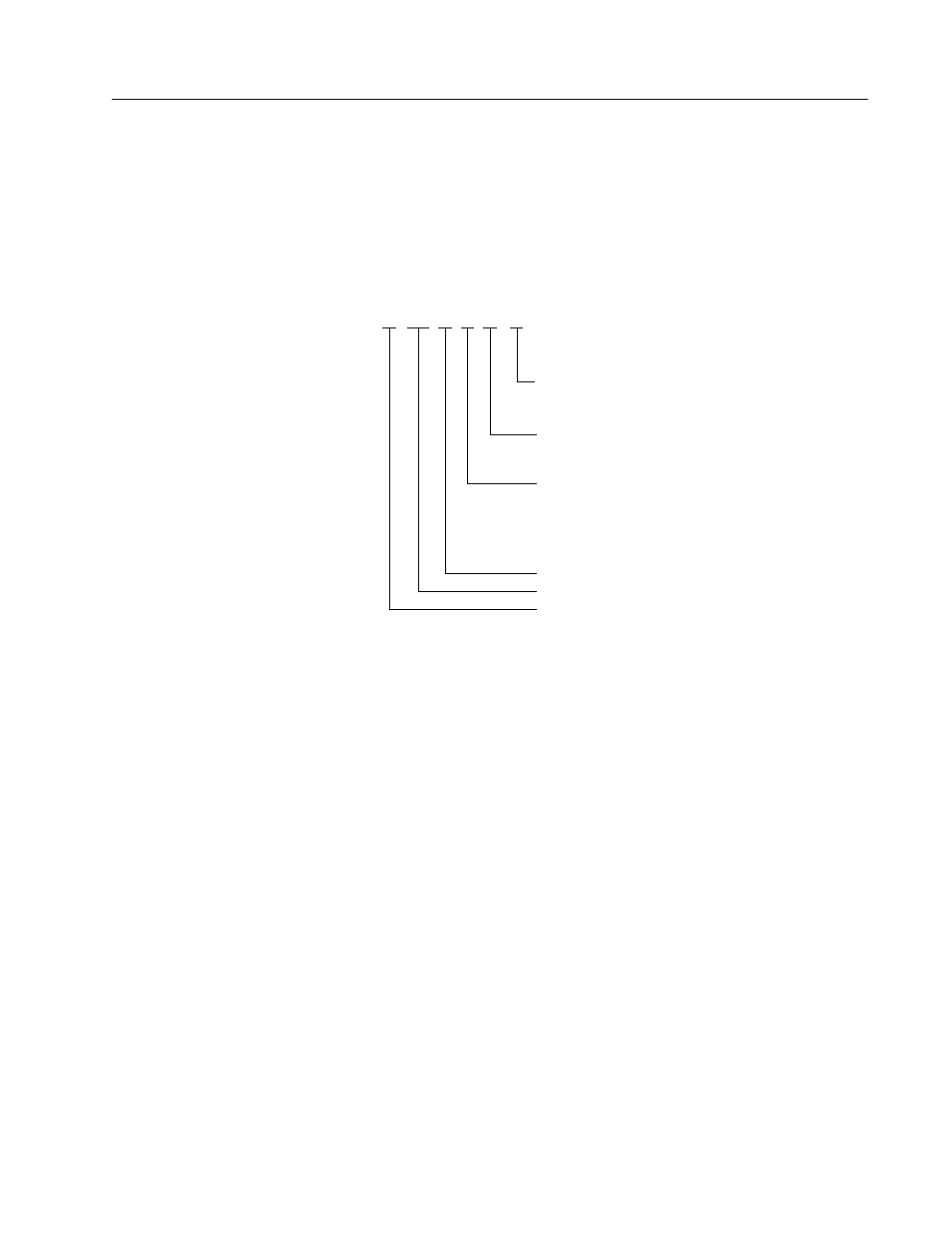
The text string translates the table ID into a real motor model number
for display. For example, the user can select the text string “H-4030-P-
H” rather than entering the table ID #23. Figure D.1 defines the text
string format of Allen-Bradley motors.
Motor Phasing
The phasing of the back-EMF and Hall feedback signals must be
verified before a custom motor file can be created. Allen-Bradley
motors use back-EMF and Hall feedback signals phased as shown in
Figure D.2. Motors not manufactured by Allen-Bradley require the
back-EMF and Hall feedback signals be phased to match those of
Allen-Bradley motors. Often this requires swapping of the R- and T-
phase control signals with each other, as well as swapping the Hall A,
Hall B, and Hall C signals with each other.
Back-EMF and Hall Signals
Figure D.2(a) shows the required phasing of the line-to-line back-
EMF signals and Figure D.2(b) shows the proper phasing of the Hall
feedback signals, when the motor is rotating clockwise (CW) as seen
looking at the motor shaft from the load.
The relationship of the Hall signals to the back-EMF signals is not
important at this stage. However, the sequencing of the back-EMF
signals must conform to Figure D.2(a), and the sequencing of the Hall
feedback signals must conform to Figure D.2(b).
Figure D.1
Allen-Bradley Motor Naming Convention
Intro
Motor Part Number
H - 4030 - P - H - 00 - AA
MOTOR WINDING K DESIGNATOR
E
SERIES DESIGNATOR
E = COMMERCIAL
F = MEDIUM INERTIA
H = LOW INERTIA
I = INDUCTION
LD = LIGHT INDUSTRIAL
N = NEMA STYLE FRAME
W = WASHDOWN
Y = LIGHT INDUSTRIAL
FRAME SIZE
FACTORY DESIGNATED SPECIAL OPTIONS
00
01
02
=
=
=
STANDARD
90 VDC BRAKE
24 VDC BRAKE
OPTICAL ENCODER LINECOUNT
F
H
J
K
L
M
N
=
=
=
=
=
=
=
1000
2000 (STANDARD)
2500
5000
500
3000
1000
FACTORY DESIGNATED SPECIAL OPTIONS
AA
AF
AG
AN
=
=
=
=
STANDARD
FLYING LEADS
IEC DIMENSIONS
NEMA 56C
FACTORY DESIGNATED SPECIAL OPTIONS
AA
= STANDARD
AF
= FLYING LEADS
AG
= IEC DIMENSIONS
AN
= NEMA 56C
FACTORY DESIGNATED SPECIAL OPTIONS
00
= STANDARD
01
= 90 VDC BRAKE
02
= 24 VDC BRAKE
OPTICAL ENCODER LINECOUNT
F
= 1000
H
= 2000 (STANDARD)
J
= 2500
K
= 5000
L
=
500
M
= 3000
N
= 1000
MOTOR WINDING K
E
DESIGNATOR
FRAME SIZE
SERIES DESIGNATOR
E
= COMMERCIAL
F
= MEDIUM INERTIA
H
= LOW INERTIA
I
= INDUCTION
N
= NEMA STYLE FRAME
W
= WASHDOWN
Y
= LIGHT INDUSTRIAL