Ac power cabling, Emergency stop contactor wiring, Tb1 – dc bus terminals – Rockwell Automation 1398-DDM-xxx USE MNL/ULTRA 200 DIG.SERVO.DR User Manual
Page 117: E 7-7, Ge 7-7
Publication 1398-5.0 – October 1998
Power Connections
7-7
AC Power Cabling
The ULTRA 200 Series drives require 100 to 240 VAC rms power
with an input frequency of 47 - 63 Hz. The 1398-DDM-010,
1398-DDM-010X, 1398-DDM-020, 1398-DDM-020X, 1398-DDM-
030 and 1398-DDM-030X require single phase input power. The
1398-DDM-075 and 1398-DDM-075X may use either single or three-
phase input power, but the 1398-DDM-150 and 1398-DDM-150X
require three-phase input power. “ULTRA 200 Series Power Ratings”
on page G-5 lists the output power characteristics of the ULTRA 200
Series drives. The AC input supplies power to the motor and the drive
logic as the default factory setting. An auxiliary power source may
provide input power to the drive I/O independent of the motor power.
Alternatively, the drive may be powered by an external DC power
source.
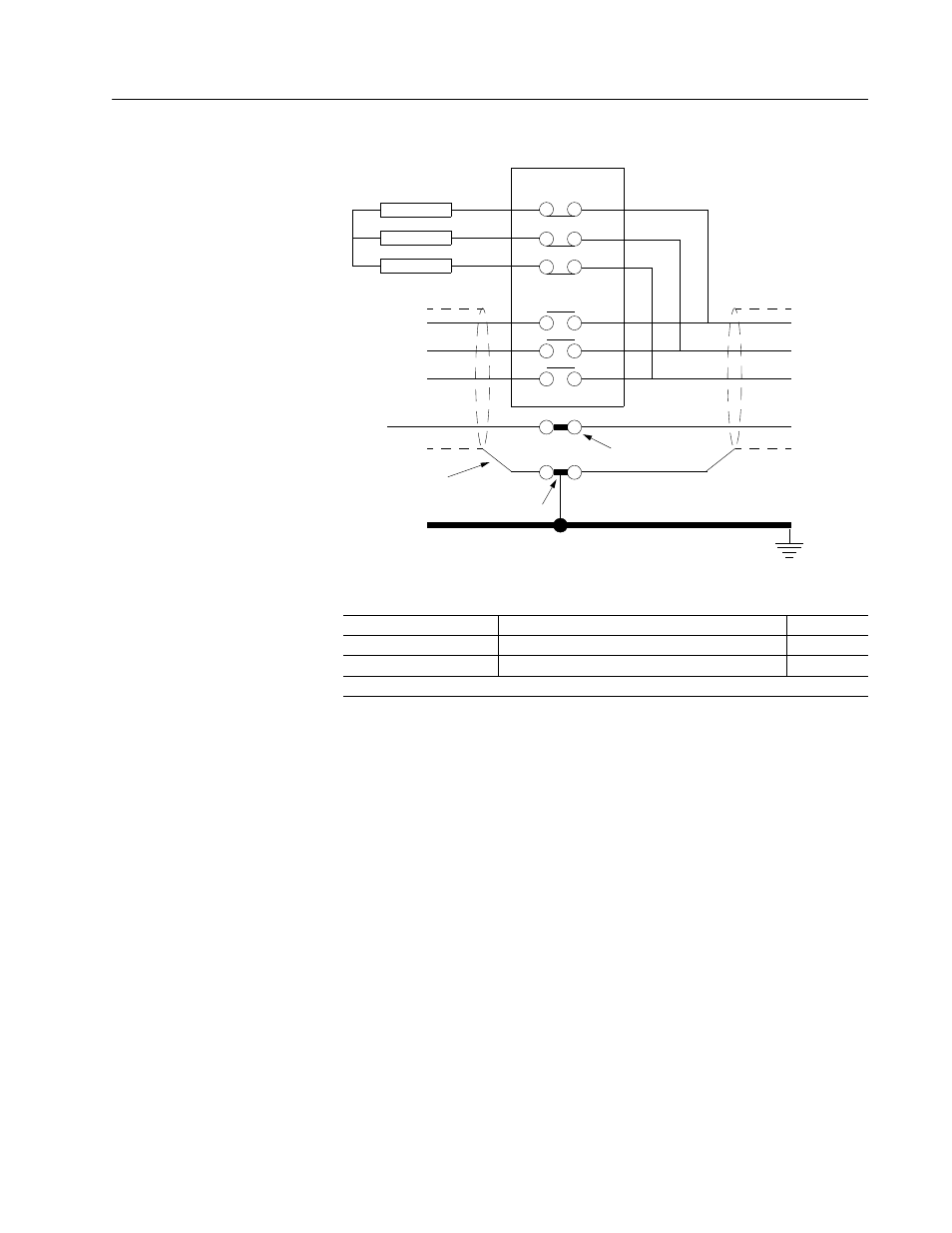
Figure 7.3
Emergency Stop Contactor Wiring
Intro
Table 7.3:
TB1 – DC Bus Terminals
Signal
Description
Terminal
DC Bus +
Positive DC Bus voltage signal
TB1-5
DC Bus -
Negative DC Bus voltage signal
TB1-6
NOTE: Torque all terminal connections to 1.25 Nm (11.0 lb-in).
R
S
T
Drive
R
S
T
Motor
GND
GND
Isolated terminal
Grounded terminal or stud
Unbraided shield
Enclosure wall
Overlapping
Contactor
Resistor
Resistor
Resistor