Filters, Position loop gains – Rockwell Automation 1398-DDM-xxx USE MNL/ULTRA 200 DIG.SERVO.DR User Manual
Page 177
Publication 1398-5.0 – October 1998
Tuning
9-7
Filters
The velocity regulator has one low pass filter. The filter bandwidth
range is from 1 Hz to 992 Hz.
The filter serves two purposes:
●
Adjust the frequency range to remove (filter) the noise produced
by encoder resolution.
●
Reduce the amount of the mechanical resonance in the
mechanical system (e.g., belt systems).
Similar results may often be achieved by reducing the update rate of
the velocity loop.
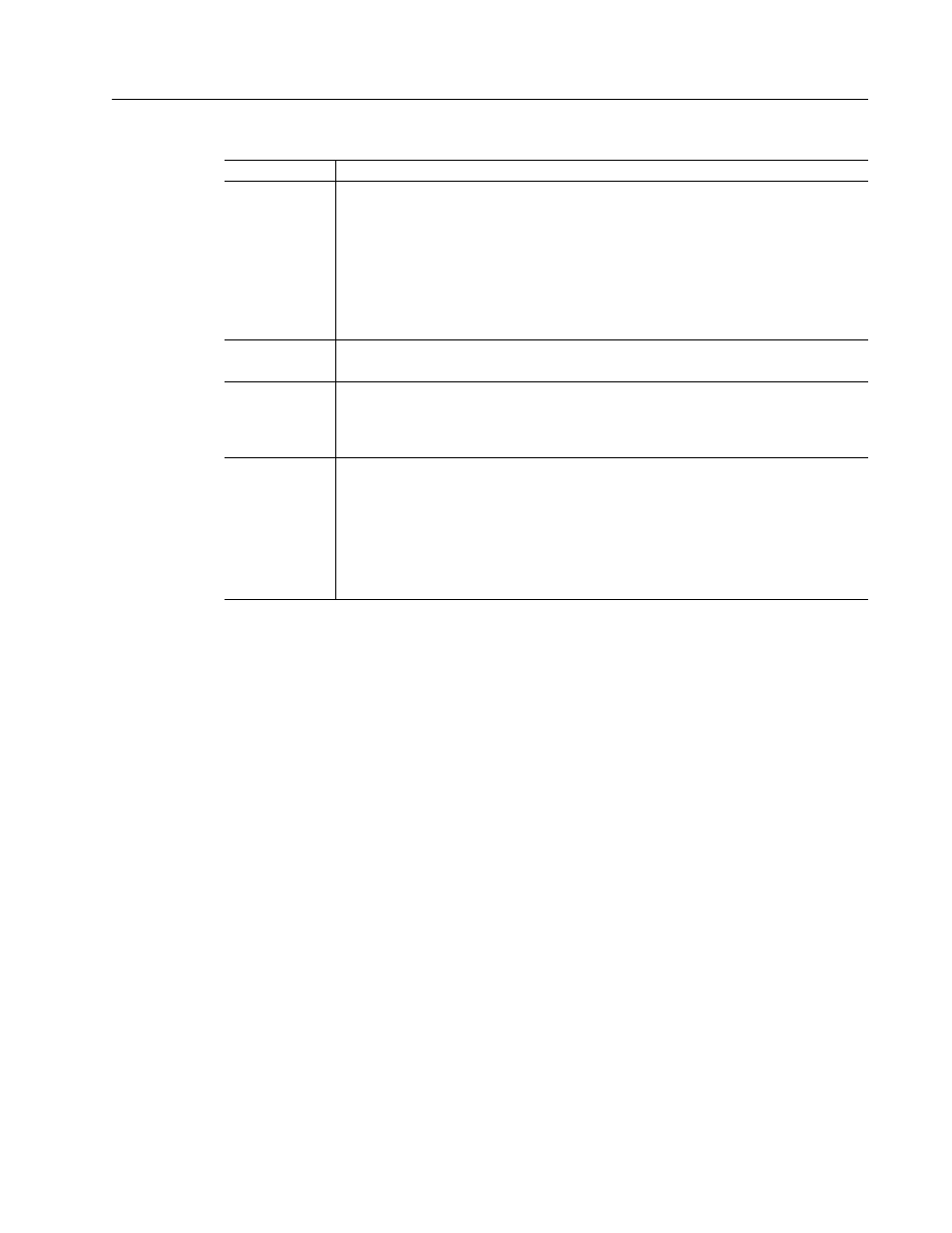
Table 9.2:
Position Loop Gains
Parameter
Description
Kp-gain
Proportional gain of the position loop.
Kp-gain changes:
• The position loop bandwidth.
• The settling time of the position loop.
In general, the higher the value of Kp-gain the faster the settling time. However, a
high value of Kp-gain with inadequate velocity loop bandwidth results in overshoot
and ringing.
Note: Kp-gain is only for use with the position following mode.
Kd-gain
Differential gain of the position loop.
Provides position loop damping and reduces overshoot caused by Kp or Ki gain.
Kff-gain
Feedforward gain of the position loop.
Kff-gain reduces following error. However, a high value of Kff-gain can result in posi-
tion overshoot. A reduction in following error allows the system to more closely
approximate gear driven systems.
Ki-gain
Integral gain of the position loop.
Ki-gain decreases the time period for the error to decay.
A non-zero value of Ki allows integration in the position loop which eliminates the
steady state following error. However, a non-zero value for Ki may introduce over-
shoot and ringing, which cause system instability (oscillation).
Note: Ki-gain is used in conjunction with the Ki Zone-value.
Ki Zone - is the area around the commanded position where Ki - gain is active.