Digital i/o power, 24 volt i/o power, 5 volt i/o power – Rockwell Automation 1398-DDM-xxx USE MNL/ULTRA 200 DIG.SERVO.DR User Manual
Page 67: 24 volt power supply specifications
Publication 1398-5.0 – October 1998
Interfaces
6-3
Digital I/O Power
ULTRA 200 Series drives provide +24VDC and +5VDC to power
external devices within the following specifications.
24 Volt I/O Power
One isolated 24 Volt power supply is accessible from the connector:
●
The allowable load is <500 mA.
●
The pin-outs are:
This supply is intended for powering the digital I/O circuitry.
The 24 VCOM is a floating ground. It must be grounded during
installation to meet the European Low Voltage Directive (LVD).
The +24 Volt power supply is internally fused by F1, a 1 Amp, fast
acting fuse. Refer to “Fuse and Jumper Locations” on page 11-4, for
the location of F1.
5 Volt I/O Power
One +5 Volt power supply is accessible from the connector:
●
The allowable load is <250 mA.
●
The pin-outs are:
This supply is intended for powering an auxiliary encoder.
The +5 Volt power supply is internally fused by F2, a 1 Amp, fast
acting fuse. Refer to “Fuse and Jumper Locations” on page 11-4, for
the location of F2.
+24VDC
J1-5
J1-26
J3-5
J3-26
24VCOM
J1-6
J1-13
J3-6
J3-13
Note: If an external +24VDC power source will power the I/O, remove
jumpers P5 and P6. Refer to “Fuse and Jumper Locations” on page 11-4,
for the location of the jumpers.
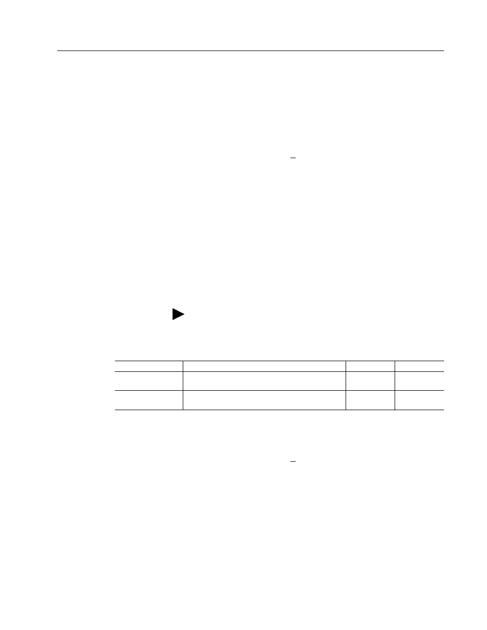
Table 6.1:
24 Volt Power Supply Specifications
Parameter
Description
Minimum
Maximum
Output Voltage
(VDC)
Voltage difference between +24VDC and
24VCOM
21.6
26.4
Output Current
(mA)
Current flow
0
500
+5 VDC
J1-1
J1-3
J3-1
J3-3
ECOM
J1-2
J1-4
J3-2
J3-4