Digital input specifications – Rockwell Automation 1398-DDM-xxx USE MNL/ULTRA 200 DIG.SERVO.DR User Manual
Page 70
Publication 1398-5.0 – October 1998
6-6
Interfaces
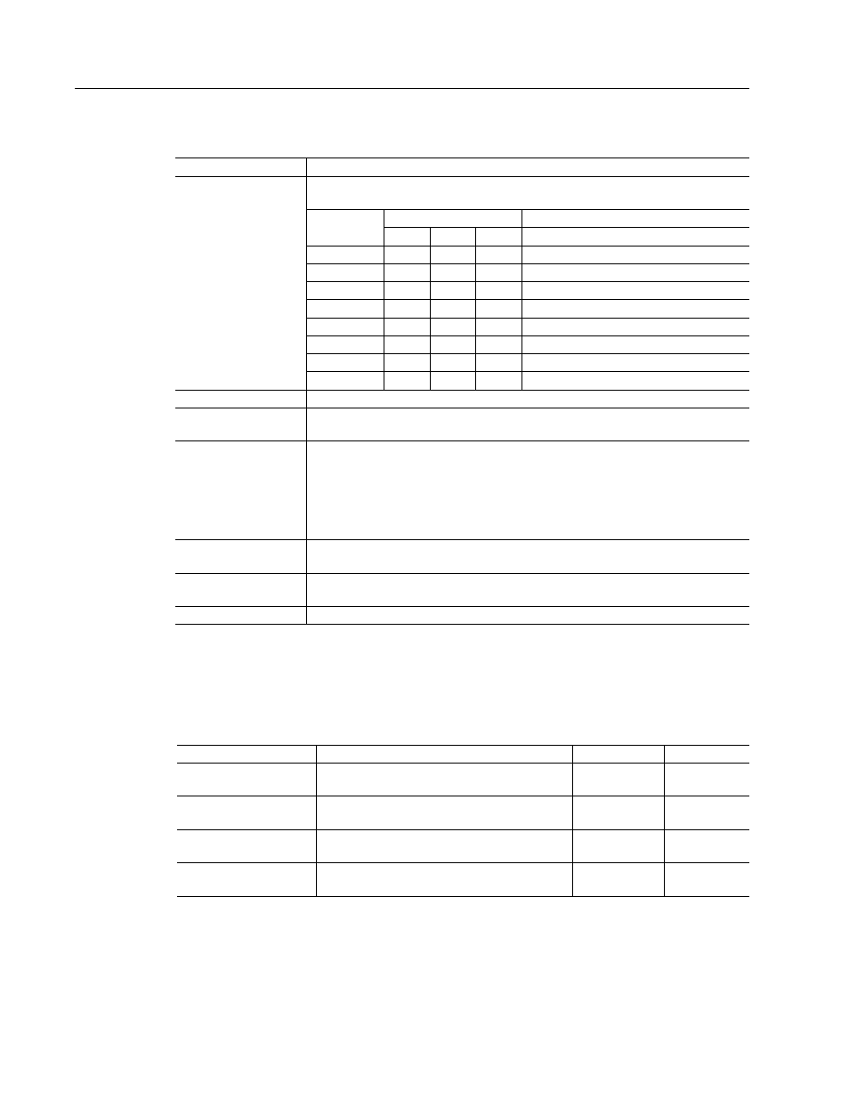
The specifications for these inputs are as follows:
Preset Select A
Preset Select B
Preset Select C
Active
a
or Inactive
b
states select one of the eight presets shown in the follow-
ing binary table:
BINARY CODE
C
B
A
Description
Preset 0
0
0
0
Preset 0 or Index 0 is selected.
Preset 1
0
0
1
Preset 1 or Index 1 is selected.
Preset 2
0
1
0
Preset 2 or Index 2 is selected.
Preset 3
0
1
1
Preset 3 or Index 3 is selected.
Preset 4
1
0
0
Preset 4 or Index 4 is selected.
Preset 5
1
0
1
Preset 5 or Index 5 is selected.
Preset 6
1
1
0
Preset 6 or Index 6 is selected.
Preset 7
1
1
1
Preset 7 or Index 7 is selected.
Start Index
A change from inactive to active starts an indexing move.
Define Home
A change from inactive to active defines the home position for absolute index-
ing.
Sensor
This selection is available only on selectable INPUT 2, and a change from
inactive to active is sensed as a registration or home sensor.
NOTE: During the homing routine with an indexing drive, an inactive to active
state transition will be registered as the home sensor, even if selectable Input 2
is not configured as registration sensor. This allows Input 2 to have a dual fea-
ture role.
Remove COMMAND
Offset
A change from inactive to active sets the offset of the analog COMMAND input
to achieve a zero command.
Fault Reset
A change from inactive to active will clear any faults and re-enable the drive, if
any faults were pending.
Start Homing
A change from inactive to active will start the homing procedure.
a. Active state indicates current flow through the input optocoupler.
b. Inactive state indicates no current flow.
Table 6.4:
INPUT1, INPUT2, INPUT3, INPUT4
and FAULT RESET Functions
(continued)
Function
Description
Table 6.5:
Digital Input Specifications
Parameter
Description
Minimum
Maximum
ON state Voltage
Voltage applied to the input to guarantee an
ON state
20 VDC
28 VDC
ON state Current
Current flow into the input to guarantee an
ON state.
3.5 mA
5.5 mA
OFF state Voltage
Voltage applied to the input to guarantee an
OFF state.
-1 VDC
3 VDC
OFF state Current
External leakage current into the input to
guarantee an OFF state.
-0.5 mA
0.5 mA