Analog inputs, Positive and negative current limit circuits, Analog inputs +i limit and -i limit – Rockwell Automation 1398-DDM-xxx USE MNL/ULTRA 200 DIG.SERVO.DR User Manual
Page 78
Publication 1398-5.0 – October 1998
6-14
Interfaces
Analog Inputs
Two types of analog input circuits are available on the J1 connector:
●
The current limiting inputs support 0 to +10 Volt signals
●
The command input supports 0 to ±10 Volt signals.
Positive Current Limit (+I LIMIT) and
Negative Current Limit (-I LIMIT)
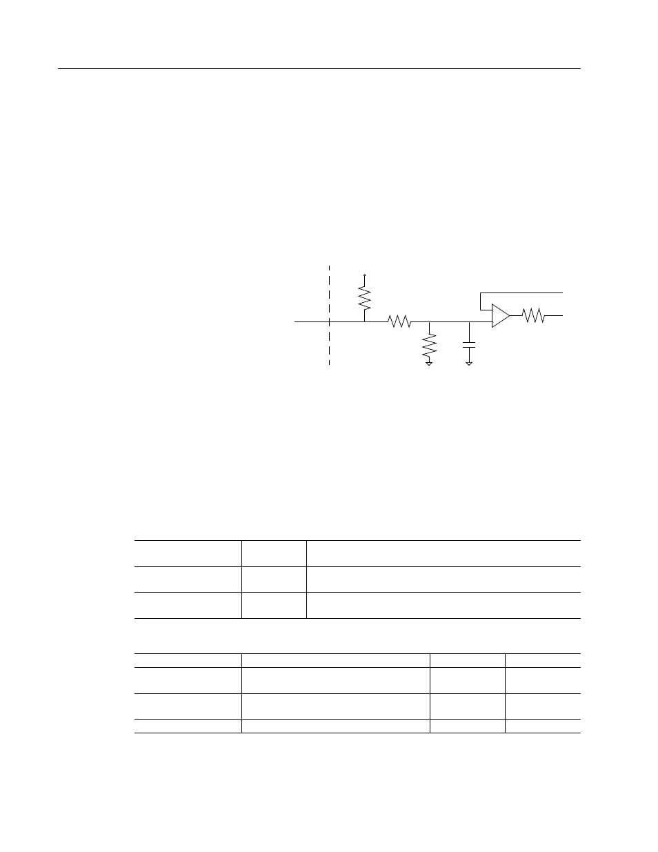
The +I LIMIT and -I LIMIT are current limit inputs to the drive. They
have a range of 0 to +10 Volts (where 10 Volts corresponds to
maximum drive current). +I LIMIT limits current for producing
positive torque, and -I LIMIT limits current for producing negative
torque. The +I LIMIT and -I LIMIT are tied together for balanced
current limiting. The analog +I LIMIT or -I LIMIT signals are
converted into a digital word by a 10-bit ADC (analog to digital
converter). If the +I LIMIT and -I LIMIT inputs are not connected,
current is not limited.
Figure 6.17
Positive and Negative Current Limit Circuits
Intro
Drive
J1
+15 Volts
10K
20K
.01
µ
F
20K
-
+
+I LIMIT or
-I LIMIT
Table 6.11:
Analog Inputs +I LIMIT and -I LIMIT
Analog Input
Pin
Number
Description
Positive Current Limit
(+I LIMIT)
J1-27
Limits the peak positive current command, which produces
positive torque.
Negative Current Limit
(-I LIMIT)
J1-29
Limits the peak negative current command, which produces
negative torque.
Table 6.12:
Positive and Negative Current Limit Imput Specification
Specification
Description
Minimum
Maximum
Resolution
Number of units that the input voltage is
converted to.
10 Bits
Maximum Current
Short circuit between the input and
ground.
-1.5 mA
Input Signal Range
Allowable voltage applied to the input.
0 Volts
+10 Volts