F- or h-series motors to ultra 200 series drive, F or h-series motor – Rockwell Automation 1398-DDM-xxx USE MNL/ULTRA 200 DIG.SERVO.DR User Manual
Page 239
Publication 1398-5.0 – October 1998
Cable Diagrams, Schematics and Examples
B-27
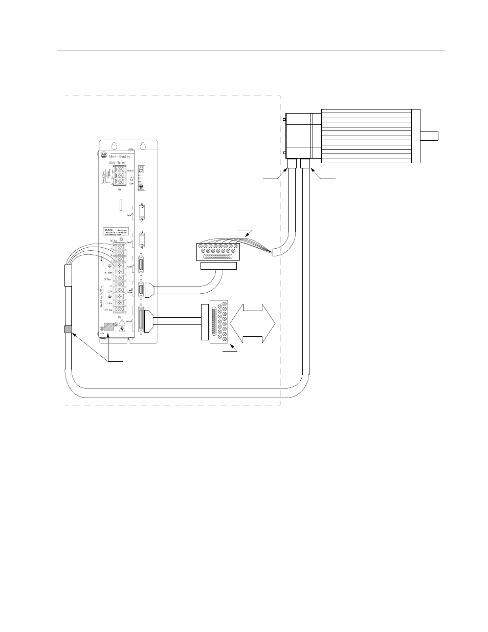
Figure B.27
F- or H-Series Motors to ULTRA 200 Series Drive
using P2 Terminal Strip
Intro
NOTES:
This wiring method provides the option to run cables through a restrictive bulkhead or enclosure.
Cable 9101-1365-XXX has a connectors on the motor end only. The cable connector is molded
and potted to the cable and may not be disassembled. Refer to the schematic for cable 9101-
1366-XXX for information on wiring this cable to the J2 Terminal Strip.
Adaptor Kit 9101-1391 includes the 3 foot cable, screw terminal strip and mounting bracket. The
cable has a 50-pin Mini D ribbon connector at the drive end and a 50-pin D connector at the termi-
nal strip end.
Adaptor Kit 9101-1392 includes the 3 foot cable, screw terminal strip and mounting bracket. The
cable has a 20-pin Mini D Ribbon connector at the drive end and a 20-pin D connector at the ter-
minal strip end.
Motor Power Cables - Use ULTRA 200 Series cables if the CE Mark is required. Other cables may
be used if the CE Mark is not an issue. In either case, the shield on the motor power cable must be
properly grounded at both ends; the shield is grounded at the motor end when the MS connector is
mated.
Motor Power Cable
Clamp exposed
to the chassis
F or H-Series Motor
Motor Power Connector
Encoder Connector
P2
9
101
-1
365
-X
XX
ground terminal
motor cable shield
Screw Terminal Strip
Enclosure/Cabinet
P1
9101-1391
To
Control
Interface
9101-1392
Screw Terminal Strip