J4 and j5–serial port, J4 and j5 – serial port, Rs-232/485 interface circuit – Rockwell Automation 1398-DDM-xxx USE MNL/ULTRA 200 DIG.SERVO.DR User Manual
Page 98: E 6-34, Ge 6-34
Publication 1398-5.0 – October 1998
6-34
Interfaces
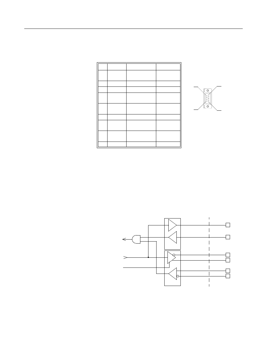
J4 and J5 – Serial Port
J4 and J5 are 9 pin female D-shell (AMP 205204-4, pins AMP 66506-
3) connectors. Each connector is a serial interface that allows
communication with another ULTRA 200 Series drive, a PC, a
terminal, a host computer, a controller or an optional TouchPad. The
signals on J4 and J5 are internally connected, which allows daisy-
chain connection of several drives. The shell of the connector is
grounded to the chassis for shield termination.
The serial interface of the ULTRA 200 Series uses the standard NRZ
asynchronous serial format, and supports both the RS-232 and the
four wire RS-485 communications standards.
●
Standard baud rates include 1200, 2400, 4800, 9600 and 19200
baud. 9600 is the factory default setting.
Pin Signal
Description
Use
1 RCV(+)
Receive (+)
RS-485
(four wire)
2 RCV
Receive
RS-232
3 XMT
Transmit
RS-232
4 XMT(+)
Transmit (+)
RS-485
(four wire)
5 COM
+5 VDC Com-
mon
6
Reserved
a
7 RCV(-)
Receive (-)
RS-485
(four wire)
8 XMT(-)
Transmit (-)
RS-485
(four wire)
9
Reserved
1
a. Do
not
connect any device to J4-6, J5-6, J4-9 or J5-9 except an Allen-Bradley TouchPad.
pin 5
pin 6
pin 9
pin 1
Figure 6.37
RS-232/485 Interface Circuit
Intro
EXT
INT
XMT
RCV
XMT-
XMT+
RCV+
RCV-
RS-232
RS-485
TRANSMIT
RECEIVE
TRANSMIT
ENABLE