Rs-232 connections, Single axis rs-232 set up, Rs-232 connection diagrams – Rockwell Automation 1398-DDM-xxx USE MNL/ULTRA 200 DIG.SERVO.DR User Manual
Page 102
Publication 1398-5.0 – October 1998
6-38
Interfaces
RS-232 Connections
The physical address is set using the 16 position rotary switch on the
front panel.
Single Axis RS-232 Set Up
A single ULTRA 200 Series drive may be selected using RS-232
communications. After cabling is attached to the unit and the drive
address is assigned, configuration of (i.e., communications with) the
unit may proceed.
The following steps outline how to select the communications
options:
1. Set the rotary switch to zero (0), which forces default communica-
tions with the drive.
2. Connect an RS-232 cable between the computer and a serial con-
nector on the drive (J4 or J5).
Note: Do not connect any device to J4-6, J5-6, J4-9 or J5-9 except an
Allen-Bradley TouchPad.
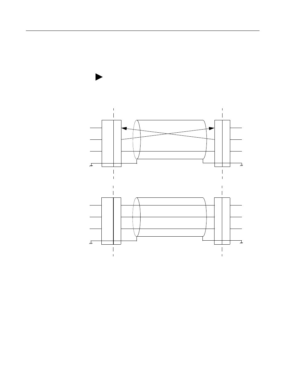
Figure 6.39
RS-232 Connection Diagrams
Intro
USER
2
9-Pin
Drive
2
Drive Chassis
PC
3
3
5
Male
RS-232 CABLE
J4 or J5
2
3
5
RCV
XMT
COM
RCV*
XMT*
COM*
* PC pin-outs
may vary by
manufacturer
9-Pin
Female
9-Pin Male Connector to 9-Pin Female Connector
9-Pin
RS-232
USER
2
9-Pin
Drive
2
Drive Chassis
PC
3
3
5
7
Male
RS-232 CABLE
J4 or J5
2
3
5
RCV
XMT
COM
XMT*
RCV*
COM*
* PC pin-outs
may vary by
manufacturer
25-Pin
Female
9-Pin Male Connector to 25-Pin Female Connector
25-Pin
RS-232
5