Connection diagram, Absolute indexing connection diagram, E figure 8.11 – Rockwell Automation 1398-DDM-xxx USE MNL/ULTRA 200 DIG.SERVO.DR User Manual
Page 164
Publication 1398-5.0 – October 1998
8-40
Application and Configuration Examples
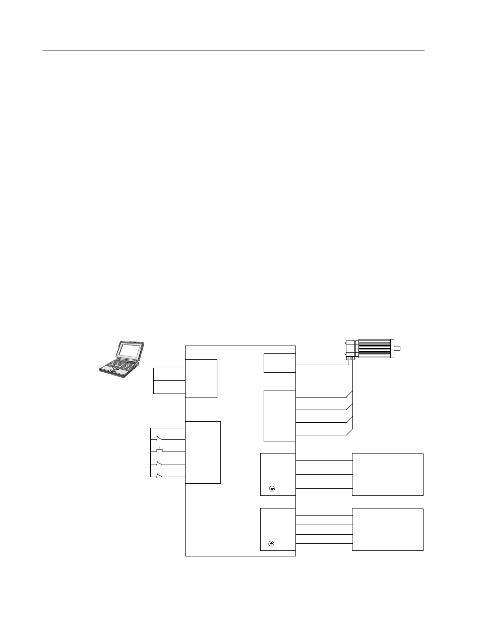
4. Connect a jumper wire with a toggle switch between the follow-
ing pins:
• J1-20 (ENABLE) and J1-26 (I/O PWR)
• J1-32 (INPUT1) and J1-26 (I/O PWR)
• J1-33 (INPUT2) and J1-26 (I/O PWR)
• J1-21 (FAULT RESET) and J1-26 (I/O PWR).
These connections provide manual control for enabling or
disabling the drive and resetting faults. The figure below shows
the jumper, including normally open toggle switches.
5. Connect the drive to a 100/240 VAC, 50/50 Hz power source
appropriate to the drive:
• Single Phase: 1398-DDM-010, 1398-DDM-010X,
1398-DDM-020, 1398-DDM-020X, 1398-DDM-030,
1398-DDM-030X, 1398-DDM-075 or 1398-DDM-075X
• Three Phase: 1398-DDM-075, 1398-DDM-075X,
1398-DDM-150 or 1398-DDM-150X
Connection Diagram
Figure 8.11
Absolute Indexing Connection Diagram
Intro
J1
J4
DRIVE
2 RCV
3 XMT
5 COM
XMT
RCV
COM
TB1
Phase R
Phase S
Phase T
Motor Gnd
J2
Motor
Encoder
1
2
3
4
L1
L2/N
Gnd
100-240 VAC
50/50 Hz
Three Phase
Power Source
L3
or
TB1
TB1
L1
L2/N
Gnd
100-240 VAC
50/50 Hz
Single Phase
Power Source
26 I/O PWR
20 ENABLE
21 FAULT
32 INPUT1
Close to ENABLE Drive
Close to RESET Fault
RESET
Close to Start INDEX
33 INPUT2
Close to Define HOME