Rockwell Automation 20D PowerFlex 700S Drive Ph I Control, Frames 1...11 User Manual
Page 97
Programming and Parameters
3-43
No.
Name
Description
Values
Li
nk
ab
le
R
ead-
Wri
te
D
ata
T
ype
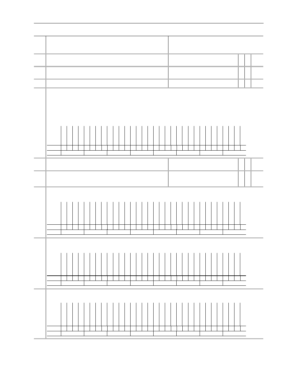
313
Heatsink Temp
Displays the measured temperature of the drive's heatsink.
Units:
Default:
Min/Max:
degC
0.0000
-30.0000/200.0000
Real
314
VPL Firmware Rev
Displays the major and minor revision levels of the drive's Velocity Position Loop (VPL)
software.
Default:
Min/Max:
Comm Scale:
1.16
0.01/99.99
x 100
16-bit
Integer
315
VPL Build Number
Displays the build number of the drive's Velocity Position Loop (VPL) software.
Default:
Min/Max:
2
1/10000
16-bit
Integer
316
SynchLink Status
Indicates status of SynchLink functions.
• Bit 0 [FB Opt Prsnt] indicates the presence of an optional feedback daughter card.
• Bit 1 [Encdr0 Prsnt] indicates the presence of Encoder 0.
• Bit 2 [Encdr1 Prsnt] indicates the presence of Encoder 1.
• Bit 3 [In Sync] indicates SynchLink communications is synchronized.
• Bit 4 [Tx Active] indicates TX frames are being transmitted downstream from this node.
• Bit 5 [Rx Active] indicates RX frames are being received from nodes upstream.
• Bit 15 [Rx Data Enbl] indicates received data is being updated.
317
SL System Time
Displays the SynchLink system time counter.
Units:
Default:
Min/Max:
µSec
0
0/
104
8575
32-bit
Integer
318
Posit Spd Output
Final output of the position regulator.
Units:
Default:
Min/Max:
Comm Scale:
RPM
0.0000
-/+14112.0000
Par 4 [Motor NP RPM] = 1.0
Real
320
Exception Event1
Indicates the presence of certain drive anomalies. Configure the drive's response to these events by entering values in the parameters of the Fault/Alarm
Configuration group of the Utility file.
321
Exception Event2
Indicates the presence of certain drive anomalies. Configure the drive's response to these events by entering values in the parameters of the Fault/Alarm
Configuration group of the Utility file.
322
Exception Event3
Indicates the presence of certain drive anomalies. Configure the drive's response to these events by entering values in the parameters of the Fault/Alarm
Configuration group of the Utility file.
Options
Res
er
ved
Res
er
ved
Res
er
ved
Res
er
ved
Res
er
ved
Res
er
ved
Res
er
ved
Res
er
ved
Res
er
ved
Res
er
ved
Res
er
ved
Res
er
ved
Res
er
ved
Res
er
ved
Res
er
ved
Res
er
ved
Rx Data Enb
l
Res
et Req
’d
Res
er
ved
Res
er
ved
Res
er
ved
Res
er
ved
Res
er
ved
Res
er
ved
Res
er
ved
Res
er
ved
Rx Ac
tiv
e
Tx
Ac
tiv
e
In
Sy
nc
Enc
dr1 Prsn
t
Enc
dr0 Prsn
t
F
B
Op
t Prs
nt
Default
0
0
0
0
0
0
0
0
0
0
0
0
0
0
0
0
0
0
0
0
0
0
0
0
0
0
0
0
0
0
0
0
Bit
31 30 29 28 27 26 25 24 23 22 21 20 19 18 17 16 15 14 13 12 11 10 9
8
7
6
5
4
3
2
1
0
0 = False
1 = True
Options
PWM A
sync
hr
o
Pr
echa
rg
e Er
MC F
ir
m
w
are
PWM S
hor
t
VPL/MC Comm
Ov
erCurre
nt
Gro
und F
ault
Tr
ans Des
at
Bus
Ov
erV
olt
MC Commi
ssn
Ov
er
F
req
In
er
tia T
est
DSP Error
DSP Mem Err
Ex
t F
aul
t I
n
In
v OL T
rip
In
v OL P
end
In
v O
T
mpT
rip
In
v O
T
mpP
end
Mo
to
r Sta
ll
Mt
r OL
P
en
d
Mt
r OL
T
ri
p
P
ow
er
Loss
SLink
Co
m
m
SLink
HW
Ctr
l EE Mem
FB Opt
1 Loss
FB Opt
0 Loss
Enc
dr1
L
oss
Enc
dr0
L
oss
SpdR
ef Dec
el
Abs
Ov
erSpd
Default
0
0
0
0
0
0
0
0
0
0
0
0
0
0
0
0
0
0
0
0
0
0
0
0
0
0
0
0
0
0
0
0
Bit
31 30 29 28 27 26 25 24 23 22 21 20 19 18 17 16 15 14 13 12 11 10 9
8
7
6
5
4
3
2
1
0
0 = False
1 = True
Options
Lgx LinkCh
ng
Lgx Closed
Lgx Timeout
Lg
x O
utO
fR
un
Ne
tL
oss DPI6
Ne
tL
oss DPI5
Ne
tL
oss DPI4
Ne
tL
oss DPI3
Ne
tL
oss DPI2
Ne
tL
oss DPI1
DP
I Los
s P6
DP
I Los
s P5
DP
I Los
s P4
DP
I Los
s P3
DP
I Los
s P2
DP
I Los
s P1
No
Ctr
l De
vc
Re
ser
ved
In
te
rp
Syn
ch
Re
ser
ved
No
nCnf
gAlar
m
V
olt
Fdbk
Los
s
Bu
sUnd
erV
olt
Ride
thruTime
Slink Mult
P
ower
E
E C
ks
m
Br
ak
eOL T
rip
PS
C Sy
s
Flt2
PS
C Sy
s
Flt1
Ctr
l E
E
Ck
sm
MC Comma
nd
+/- 12
v
Pwr
Default
0
0
0
0
0
0
0
0
0
0
0
0
0
0
0
0
0
0
0
0
0
0
0
0
0
0
0
0
0
0
0
0
Bit
31 30 29 28 27 26 25 24 23 22 21 20 19 18 17 16 15 14 13 12 11 10 9
8
7
6
5
4
3
2
1
0
0 = False
1 = True
Options
Re
se
rv
ed
Re
se
rv
ed
Re
se
rv
ed
Re
se
rv
ed
Re
se
rv
ed
Re
se
rv
ed
Re
se
rv
ed
Re
se
rv
ed
Re
se
rv
ed
Re
se
rv
ed
Re
se
rv
ed
Po
si
t E
rr
-Hrd
Ov
rT
rv
l
+
H
rd
Ov
rT
rv
l
-Sft
Ov
rT
rv
l
+Sf
t Ov
rT
rv
l
Re
se
rv
ed
Re
se
rv
ed
Re
se
rv
ed
Re
se
rv
ed
Re
se
rv
ed
H
H PwrBdT
emp
H
H PwrEE
Er
H
HPrCh
rg
Cntc
H
H
PwrBd
Prc
HH
D
rv
O
vr
ld
H
H
F
anF
dbkL
s
H
H
Bu
sWtc
hDg
H
H
Bu
sCRC
Er
HH
B
us
Lin
kL
s
H
H Bu
sComDly
HH
In
P
has
eL
s
Default
0
0
0
0
0
0
0
0
0
0
0
0
0
0
0
0
0
0
0
0
0
0
0
0
0
0
0
0
0
0
0
0
Bit
31 30 29 28 27 26 25 24 23 22 21 20 19 18 17 16 15 14 13 12 11 10 9
8
7
6
5
4
3
2
1
0
0 = False
1 = True