Rockwell Automation 20D PowerFlex 700S Drive Ph I Control, Frames 1...11 User Manual
Page 111
Programming and Parameters
3-57
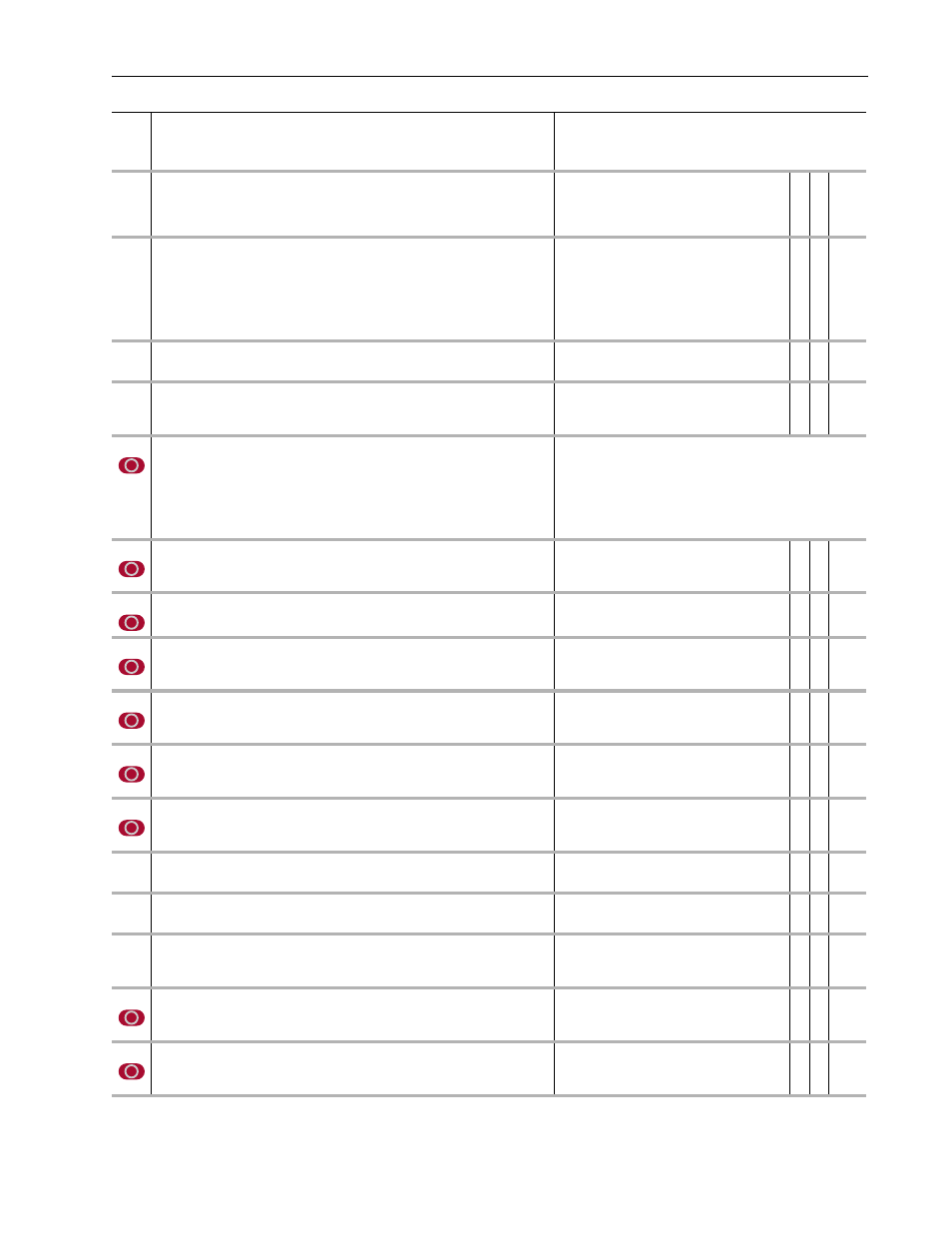
474
Freq Reg We BW
Sets the electrical (stator) frequency bandwidth for the Frequency Regulator, which
estimates motor speed when sensorless feedback is selected.
Must always be set to a value higher than Par 475 [Freq Reg Wr BW].
Default:
Min/Max:
150
0/32767
✓ 16-bit
Integer
475
Freq Reg Wr BW
Sets the rotor (speed) frequency bandwidth for the Frequency Regulator, which estimates
motor speed when sensorless feedback is selected.
Must always be set to a value higher than Par 97 [Act Spd Reg BW]. Normal applications
should use a value approximately 50% greater than Par 97. Applications with large
dynamic ranges can use values 200-300% greater than Par 97. However large values
can result in pull-outs and unstable operation.
Default:
Min/Max:
30
0/32767
✓ 16-bit
Integer
476
Slip Gain Comp
Provides slip gain compensation for sensorless speed adjustment.
Units:
Default:
Min/Max:
%
100.00
0.00/400.00
✓ 16-bit
Integer
477
Est Theta Delay
Active only in Permanent Magnet motor mode (when Par 485 [Motor Ctrl Mode] equals 2
“PMag Motor”). Provides a delay for the function that compares the estimated rotor
position and the data from the position sensor.
Units:
Default:
Min/Max:
mSec
10
2/1024
✓ 16-bit
Integer
485
Motor Ctrl Mode
Enter a value to select the operating mode for the Motor Control (MC).
• 0 “FOC” - (Field Oriented Control) is induction motor control with voltage adaptation.
• 1 “FOC 2” (Field Oriented Control 2) is induction motor control with temperature
adaptation.
• 2 “Pmag Motor” - (Permanent Magnet Motor Control) is permanent magnet motor
operation.
• 4 (Test) - Is the test mode.
Default:
Options:
0
0
1
2
“FOC”
“FOC”
3
“Reserved”
“FOC 2”
4
“Test”
“PMag Motor”
486
Rated Slip Freq
Displays the control slip frequency, determined from Par 3 [Motor NP Hertz] and Par 4
[Motor NP RPM]. Measured by the autotune procedure. Do not change this value.
Units:
Default:
Min/Max:
Comm Scale:
Hz
0.470
0.000/32.000
x 1000
✓ 16-bit
Integer
487
Motor NTC Coef
Defines a coefficient used to calculate the rotor temperature from the measured stator
temperature. Used only in Field Oriented Control - 2 (FOC2) mode.
Units:
Default:
Min/Max:
%
100
50/200
✓ 16-bit
Integer
488
Flux Current
Specifies the magnetizing current that produces rated flux in the motor in a per unit
(percent representation). Measured by the autotune procedure. Do not change this value.
Units:
Default:
Min/Max:
Comm Scale:
%
30.00
0.00/75.00
x 100
✓ 16-bit
Integer
490
StatorInductance
Displays the sum of the stator and cable inductances of the motor in per unit (percent
representation), as determined by the autotune procedure. Scaled to percent of rated
motor impedance. Do not change this value.
Units:
Default:
Min/Max:
Comm Scale:
%
100.00
0.00/799.99
100 = 8192\
✓ 16-bit
Integer
491
StatorResistance
Displays the sum of the stator and cable resistances of the motor in per unit (percent
representation), as determined by the autotune procedure. Scaled to percent of rated
motor impedance. Do not change this value.
Units:
Default:
Min/Max:
Comm Scale:
%
1.00
0.00/100.00
100 = 8192
✓ 16-bit
Integer
492
Leak Inductance
Displays the sum of the motor stator, rotor leakage, and motor cable inductances in per
unit (percent representation), as determined by the autotune procedure. Scaled to
percent of rated motor impedance. Do not change this value.
Units:
Default:
Min/Max:
Comm Scale:
%
20.00
0.00/100.00
100 = 8192
✓ 16-bit
Integer
493
Leak Indc Sat 1
Displays the leakage inductance correction for the first overload level as determined by
the autotune procedure.
Units:
Default:
Min/Max:
%
100.00
25.00/100.00
16-bit
Integer
494
Leak Indc Sat 2
Displays the leakage inductance correction for the first overload level as determined by
the autotune procedure.
Units:
Default:
Min/Max:
%
100.00
25.00/100.00
16-bit
Integer
500
Bus Util Limit
Sets the maximum allowed bus voltage utilization for the Motor Control. Do not change
this value. Higher values may result in control instability or over-current faults.
Units:
Default:
Min/Max:
Comm Scale:
%
90.0
0.0/100.0
100 = 8192
✓ 16-bit
Integer
501
Torque En Dly
Sets the delay between the time the drive is enabled and the time the Motor Control
applies torque.
Units:
Default:
Min/Max:
Comm Scale:
mSec
100
0/32767
100 = 8192
✓ 16-bit
Integer
502
Rotor Resistance
Displays rotor resistance, as determined by the autotune procedure. Scaled to percent of
rated motor impedance. Do not change this value.
Units:
Default:
Min/Max:
Comm Scale:
%
1.00
0.00/100.00
100 = 8192
✓ 16-bit
Integer
No.
Name
Description
Values
Li
nkab
le
Read
-Wr
it
e
Da
ta
T
ype