Powerflex 700s, Block diagrams, B-2 control block diagrams – Rockwell Automation 20D PowerFlex 700S Drive Ph I Control, Frames 1...11 User Manual
Page 194
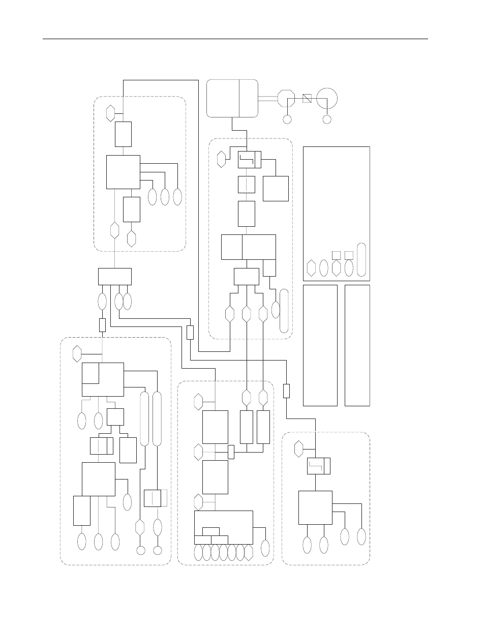
B-2
Control Block Diagrams
( )= Enumerated Parameter
[ ]= Page and Coordinate
ex. 3A2 = pg 3, Column A, Row 2
Definations of the Per Unit system:
1
.0 PU Position = Distance traveled in 1sec at Base Spd
1.0 PU Speed = Base Speed of the Motor
1.0 PU Torque = Base Torque of the Motor
PowerFlex 700S
Block Diagrams
Link
Link
Read Only Parameter
Read / Write Parameter
Read Only Parameter with Bit Enumeration
Read / Write Parameter with Bit Enumeration
Provides additional information
PI Regulator
181
182
PI Reference
PI Feedback
Limit
186
187
PI Prop Gain
PI Integ Time
Process Control (2ms)
180
PI Output
Speed Ref
Selection
Linear
Ramp &
S Curve
16
Speed Ref Sel
40
Lead Lag
46
43
Friction Comp
Inertia Comp
Speed Control - Reference (2ms)
145
59
Selected Spd Ref
S Curve Spd Ref
Scaled Spd Ref
10
11
12
13
14
15
20
/
*
+
Link
+
Torque
Selection
*, /, +
302
145
59
xxx
Spd Reg PI Out
FricComp TorqAdd
Inertia Torq Add
Torque Ref Inputs
Bus Volt
& Power
Regulator
Notch
Control
Drive
& Motor
Protection
1
Flux
305
Mtr TorqCurr Ref
Torque Control (0.5ms)
Limit
PI Regulator
81
82
Spd Reg P Gain
Spd Reg I Gain
Lead Lag
Lead Lag
300
Motor Spd
Fdbk
302
Spd Reg PI Out
Speed Control - Regulator (0.5ms)
Motor Speed Ref
90
Spd Reg BW
301
Link
+
22
23
21
Speed Trim 3
FOC
Perm Magn
& Vector
Control
Current
Processing
Motor
Load
E
1
E
2
Gear
Position
Interpolator
Reference
Selection
(Mode)
748
743
758
CoarsePosit Trgt
Aux Posit Ref
Pt-Pt Posit Ref
742
Posit Ref Sel
Gear Rat
[ N ]
[ D ]
764
Posit Load Fdbk
+
Position
Offset
PI Regulator
Point to
Point
770
768
PositReg P Gain
Posit Reg Integ
762
Mtr Posit FB
Proportional Channel
Integration Channel
318
Posit Spd Output
Position Control (2ms)
Gear Rat
[ N ]
[ D ]
E
2
E
1
2