Rockwell Automation 20D PowerFlex 700S Drive Ph I Control, Frames 1...11 User Manual
Page 124
3-70
Programming and Parameters
733
Data Out C1 Real
Link C Word 1 (Real or Floating Point) - Parameter number whose value will be written to
a communications device data table.
Default:
Min/Max:
0.0000
-/+2200000000.0000
✓ ✓ Real
734
Data Out C2 Int
Link C Word 2 (Integer) - Parameter number whose value will be written to a
communications device data table.
Default:
Min/Max:
0
-/+2147483648
✓ ✓ 32-bit
Integer
735
Data Out C2 Real
Link C Word 2 (Real or Floating Point) - Parameter number whose value will be written to
a communications device data table.
Default:
Min/Max:
0.0000
-/+2200000000.0000
✓ ✓ Real
736
Data Out D1 Int
Link D Word 1 (Integer) - Parameter number whose value will be written to a
communications device data table.
Default:
Min/Max:
0
-/+2147483648
✓ ✓ 32-bit
Integer
737
Data Out D1 Real
Link D Word 1 (Real or Floating Point) - Parameter number whose value will be written to
a communications device data table.
Default:
Min/Max:
0.0000
-/+2200000000.0000
✓ ✓ Real
738
Data Out D2 Int
Link D Word 2 (Integer) - Parameter number whose value will be written to a
communications device data table.
Default:
Min/Max:
Comm Scale:
0
-/+2147483648
x 1
✓ ✓ 32-bit
Integer
739
Data Out D2 Real
Link D Word 2 (Real or Floating Point) - Parameter number whose value will be written to
a communications device data table.
Default:
Min/Max:
0.0000
-/+2200000000.0000
✓ ✓ Real
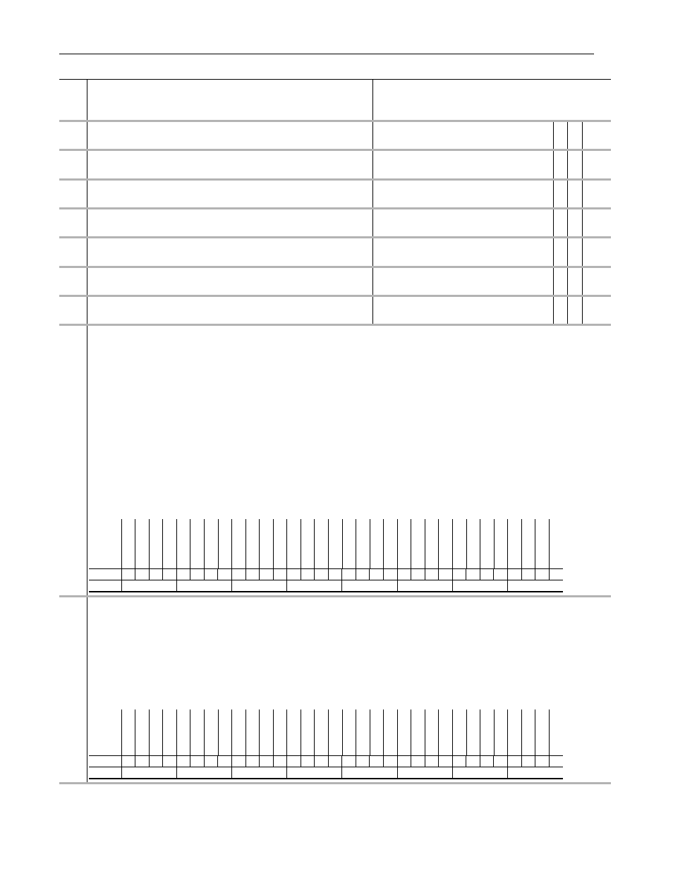
740
Position Control
Set bits to enable various position control functions.
• Setting bit 1 [Speed Out En] enables position regulator output at Par 318 [Posit Spd Output].
• Setting bit 2 [Integ En] enables integrator operation. Resetting it resets the integrator.
• Setting bit 3 [Integ Hold] holds the integrator in the present state.
• Setting bit 4 [X Offset Pol] reverses polarity of offset parameters.
• Setting bit 5 [XOffset ReRef] permits changing the value of position offsets without changing actual position. Resetting it makes the position offset relative to the
re-referenced value or the latched value upon enable if re-reference was not performed.
• Bit 6 [ActPosit Rst] is only operational when Bit 8 [Xzero Preset] is off. When bit 6 [ActPosit Rst] is set, Pars 744 [PositRef EGR Out], 747 [Position Cmmd], 763
[Act Motor Posit] and 765 [Posit Actl Load] will be set to the value of Par 762 [Mtr Posit Fdbk] upon drive enable. When bit 6 [ActPosit Rst] is cleared, the above
four parameters are set to a value of the position reference selected by Par 743 [Aux Posit Ref].
• Setting bit 7 [AbsoluteMode] puts the position regulator in Absolute mode.
• Setting bit 8 [Xzero Preset] presets Pars 744 [PositRef EGR Out], 747 [Position Cmmd], 763 [Act Motor Posit] and 765 [Posit Actl Load] to the value in Par 762 [Mtr
Posit Fdbk] minus Par 757 [Abs Posit Offset] upon drive enable.
• Setting bit 10 [Pt-Pt ReRef] enables setting or changing Par 758 [Pt-Pt Posit Ref] without changing actual position.
• Setting bit 16 [X Watch1 En] enables position Watch 1. Resetting it clears Par 741 [Position Status] bit 8 [Posit Watch1].
• Setting bit 17 [X Watch1 Dir] causes Position Watch 1 output to be set when Par 763 [Act Motor Posit] is greater than Par 780 [PositDtct1 Stpt]. Re-setting bit 17 [X
Watch1 Dir] causes Position Watch 1 output to be set when Par 763 [Act Motor Posit] is less than Par 780 [PositDtct1 Stpt].
• Setting bit 18 [X Watch2 En] enables position Watch 2. Resetting it clears Par 741 [Position Status] bit 9 [Posit Watch2].
• Setting bit 19 [X Watch2 Dir] causes Position Watch 2 output to be set when Par 763 [Act Motor Posit] is greater than Par 781 [PositDtct2 Stpt]. Re-setting bit 19 [X
Watch2 Dir] causes Position Watch 2 output to be set when Par 763 [Act Motor Posit] is less than Par 781 [PositDtct2 Stpt].
741
Position Status
Indicates status of position control algorithms.
• Bit 0 [X IGain LLim] indicates the position integrator is at the lower limit.
• Bit 1 [X IGain HLim] indicates the position integrator is at the high limit.
• Bit 2 [X Spd LLim] indicates the position regulator output at the low limit.
• Bit 3[X Spd HLim] indicates the position regulator output is at the high limit.
• Bit 4 [PtPtRRef Act] TBD.
• Bit 5 [XOffRRef Act] TBD.
• Bit 7 [Regulator On] indicates position regulator is active.
• Bit 8 [Posit Watch1] indicates Position Watch 1 has detected motor position equal to its setpoint, from the proper direction.
• Bit 9 [Posit Watch2] indicates Position Watch 2 has detected motor position equal to its setpoint, from the proper direction.
• Bit 10 [In Position] indicates Par 769 [Position Error] is within the position deadband specified by parameter 782 [In Posit BW].
No.
Name
Description
Values
Li
nkab
le
Read
-Wr
it
e
Da
ta
T
ype
Options
Res
er
ve
d
Res
er
ve
d
Res
er
ve
d
Res
er
ve
d
Res
er
ve
d
Res
er
ve
d
Res
er
ve
d
Res
er
ve
d
Res
er
ve
d
Res
er
ve
d
Res
er
ve
d
Res
er
ve
d
X W
atch2
Dir
X W
atch2
En
X W
atch1
Dir
X W
atch1
En
Res
er
ve
d
Res
er
ve
d
Res
er
ve
d
Res
er
ve
d
Res
er
ve
d
Pt-P
t ReRe
f
Res
er
ve
d
Xz
er
o Pr
eset
Abs
olut
eMode
Ac
tP
osit Rs
t
XOffs
et Re
Ref
X Of
fs
et
P
ol
In
te
g Ho
ld
In
te
g En
Spe
ed Out
En
Res
er
ve
d
Default
0
0
0
0
0
0
0
0
0
0
0
0
1
0
1
0
0
0
0
0
0
0
0
1
0
0
0
0
0
0
1
0
Bit
31 30 29 28 27 26 25 24 23 22 21 20 19 18 17 16 15 14 13 12 11 10 9
8
7
6
5
4
3
2
1
0
0 = False
1 = True
Options
Rese
rv
ed
Rese
rv
ed
Rese
rv
ed
Rese
rv
ed
Rese
rv
ed
Rese
rv
ed
Rese
rv
ed
Rese
rv
ed
Rese
rv
ed
Rese
rv
ed
Rese
rv
ed
Rese
rv
ed
Rese
rv
ed
Rese
rv
ed
Rese
rv
ed
Rese
rv
ed
Rese
rv
ed
Rese
rv
ed
Rese
rv
ed
Rese
rv
ed
Rese
rv
ed
In
P
osi
tio
n
P
osi
t W
atc
h2
P
osi
t W
atc
h1
Regulat
or
On
Rese
rv
ed
XOffRRef Act
PtP
tRRe
f Ac
X S
pd
HLim
X S
pd
LLim
X I
Gain
HLim
X I
G
ain
LLim
Default
0
0
0
0
0
0
0
0
0
0
0
0
1
0
1
0
0
0
0
0
0
0
0
1
0
0
0
0
0
0
1
0
Bit
31 30 29 28 27 26 25 24 23 22 21 20 19 18 17 16 15 14 13 12 11 10 9
8
7
6
5
4
3
2
1
0
0 = False
1 = True