Figure 1.4 power terminal block, Installation/wiring 1-13, Frame 1 – Rockwell Automation 20D PowerFlex 700S Drive Ph I Control, Frames 1...11 User Manual
Page 27: Frame 2, Frame 3
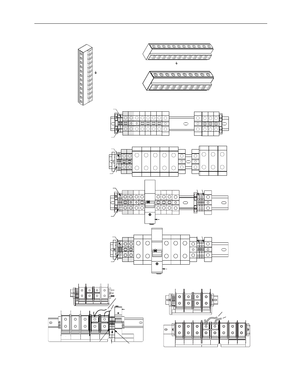
Installation/Wiring
1-13
Figure 1.4 Power Terminal Block
BR1
BR2
DC+
DC–
PE
U (T1)
V (T2)
W (T3)
R (L1)
S (L2)
T (L3)
240
VAC
120
VAC
0
VAC
PE
PE
W/T3
V/T2
U/T1
DC–
DC+
BR1*/
DC+
BR2*
PS–
PS+
Precharge Resistor Fuse – FWP-15A14F
(Common Bus Drives w/Precharge Only)
240
VAC
120
VAC
0
VAC
PE
PE
W/T3
V/T2
Precharge Resistor Fuse – FWP-15A14F
(Common Bus Drives w/Precharge Only)
U/T1
DC–
DC+
BR1*/
DC+
BR2*
PS–
PS+
Frame 1
T
(L3)
S
(L2)
R
(L1)
W
(T3)
V
(T2)
U
(T1)
PE
DC–
DC+
BR2
BR1
Frame 2
T
(L3)
S
(L2)
R
(L1)
W
(T3)
V
(T2)
U
(T1)
DC–
DC+
BR2
BR1
Frame 3
T/L3
S/L2
R/L1
PE
PE
W/T3
V/T2
U/T1
DC–
DC+
BR1/
DC+
BR2
PS–
PS+
Frame 5 - 75 HP, Normal Duty
480V AC Input
Frame 5 - 100 HP, Normal Duty
480V AC Input
Shaded terminals (BR1 & BR2) will only be present on drives ordered with the Brake Option.
T/L3
S/L2
R/L1
PE
PE
W/T3
V/T2
U/T1
DC–
DC+
BR1/
DC+
BR2
PS–
PS+
Frame 5 - 75 HP, Normal Duty
650V DC Input
Frame 5 - 100 HP, Normal Duty
650V DC Input
USE 75 C
COPPER WIRE
ONLY
TORQUE
52 IN-LB
(6 N-M)
U
T1
DC–
DC+
BR1
BR2
V
T2
W
T3
R
L1
S
L2
INPUT
OUTPUT
T
L3
PE
PE
USE 75 C COPPER WIRE ONLY, TORQUE 52 IN-LB (6 N-M)
22-10
AWG
5.3 IN-LB
(0.6 N-M)
WIRE STRIP
PS+
PS–
Common Mode Capacitor
& MOV Jumpers
Input Filter Capacitor
Frame 6 - 150 HP, Normal Duty
480 V AC Input
DC–
DC+
BR1
BR2
USE 75 C COPPER WIRE ONLY, TORQUE 52 IN-LB (6 N-M)
22-10
AWG
5.3 IN-LB
(0.6 N-M)
WIRE STRIP
PS+
PS–
U
T1
V
T2
W
T3
PE
PE
USE 75 C
COPPER WIRE
ONLY
TORQUE
52 IN-LB
(6 N-M)
OUTPUT
22-10 AWG
5.3 IN-LB
(0.6 N-M)
FAN
INPUT
1-PHASE
0 VAC
120 VAC
240 VAC
Precharge Resistor Fuse – FWP-15A14F
(Common Bus Drives w/Precharge Only)
Common Mode Capacitor
& MOV Jumpers
Input Filter Capacitor
Frame 6 - 150 HP, Normal Duty
650V DC Input
0 VAC
240V AC
120V AC