Rockwell Automation 20D PowerFlex 700S Drive Ph I Control, Frames 1...11 User Manual
Page 129
Programming and Parameters
3-75
796
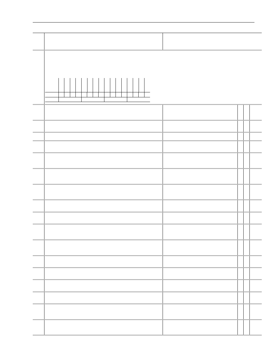
Posit Index Ctrl
Set bits to control the Position Index function.
• Setting bit 0 [Enable] allows the Position Index function to run.
• Setting bit 1 [Step] causes Par 799 [PositIndexOutput] to change by the amount in Par 797 [Posit Index Step] if bit 0 [Enable] is on.
• Setting bit 2 [Reverse] causes Par 799 [PositIndexOutput] to decrement by the value in Par 797 [Posit Index Step] instead of increment if bit 0 [Enable] is on.
• Setting bit 3 [Preset] forces the value in Par 798 [PositIndexPreset] into Par 799 [PositIndexOutput] if bit 0 [Enable] is set. Bit 3 [Preset] overrides bits 1 [Step] and
2 [Reverse].
797
Posit Index Step
Specifies the amount added to or subtracted from Par 799 [PositIndexOutput] on the
rising edge of Par 796 [Posit Index Ctrl], bit 1 [Step]. Note that this value can be positive
and negative.
Default:
Min/Max:
0
-/+2147483648
✓ ✓ 32-bit
Integer
798
PositIndexPreset
Specifies the value to be moved into Par 799 [PositIndexOutput] when Par 796 [Posit
Index Ctrl], bits 0 [Enable] and 3 [Preset] are on.
Default:
Min/Max:
0
-/+2147483648
✓ ✓ 32-bit
Integer
799
PositIndexOutput
Displays the output of the Position Index function.
Default:
Min/Max:
0
-/+2147483648
32-bit
Integer
800
Anlg In1 Data
Displays the value of Analog Input 1. This is the final value (after conversion, offsetting,
scaling and filtering).
Default:
Min/Max:
0.0000
-/+2200000000.0000
Real
801
Anlg In1 Volts
Displays the sum of Par 803 [Anlg In1 Offset] and the analog to digital conversion of
Analog Input 1. The display range is +/-10V. If switch SW1-1 is closed (set for +/-1.0V) the
value is scaled and displayed as +/-10V.
Units:
Default:
Min/Max:
Volt
0.0000
-/+10.0000
Real
802
Anlg In1 Scale
Scales the range of Analog Input 1 to the range of Par 800 [Anlg In1 Data]. Par 801 [Anlg
In1 Volts] is multiplied by this number to produce the input to the lead lag filter function.
Par 802 = 1 and Par 800 = 10 when 10V is applied.
Units:
Default:
Min/Max:
/1v
0.0000
-/+2200000000.0000
✓ ✓ Real
803
Anlg In1 Offset
Applies an offset to Analog Input 1. The output of the analog to digital conversion is
summed with this number to produce Par 801 [Anlg In1 Volts]. This is used to zero out the
analog input.
Units:
Default:
Min/Max:
Volt
0.0000
-/+20.0000
✓ ✓ Real
804
AI 1 Filt Gain
Provides the lead term for the Analog Input 1 filter. A values greater than 1 will result in a
lead function and a value less than 1 will result in a lag function.
Default:
Min/Max:
1.0000
-/+5.0000
✓ ✓ Real
805
Anlg In1 Filt BW
Sets the frequency for the Analog Input 1 filter.
Units:
Default:
Min/Max:
R/S
0.0000
0.0000/3760.0000l
✓ ✓ Real
806
Anlg In2 Data
Displays the value of Analog Input 2. This is the final value (after conversion, offsetting,
scaling and filtering).
Units:
Default:
Min/Max:
Comm Scale:
0.0000
-/+2200000000.0000
x 1
Real
807
Anlg In2 Volts
Displays sum of the Par 809 [Anlg In2 Offset] and the analog to digital conversion of
Analog Input 1. The display range is +/-10V. If switch SW1-1 is closed (set for +/-1.0V) the
value is scaled and displayed as +/-10V.
Units:
Default:
Min/Max:
Volt
0.0000
-/+10.0000
Real
808
Anlg In2 Scale
Scales the range of Analog Input 2 to the range of Par 806 [Anlg In2 Data]. Par 807 [Anlg
In2 Volts] is multiplied by this number to produce the input to the lead lag filter function.
Units:
Default:
Min/Max:
/1v
0.0000
-/+2200000000.0000
✓ ✓ Real
809
Anlg In2 Offset
Applies an offset to Analog Input 2. The output of the analog to digital conversion is
summed with this number to produce Par 807 [Anlg In2 Volts].
Units:
Default:
Min/Max:
Volt
0.0000
-/+20.0000
✓ ✓ Real
810
AI 2 Filt Gain
Provides the lead term for the Analog Input 2 filter. A values greater than 1 will result in a
lead function and a value less than 1 will result in a lag function.
Default:
Min/Max:
1.0000
-/+5.0000
✓ ✓ Real
811
Anlg In2 Filt BW
Sets the frequency for the Analog Input 2 filter.
Units:
Default:
Min/Max:
R/S
0.0000
0.0000/3760.0000
✓ ✓ Real
812
Anlg Out1 Offset
Provides an offset for Analog Output 1, before the scaling and limit blocks in the Analog
Output 1 function. This parameter is summed with either Par 814 [AnlgOut1 Integer] or
815 [Anlg Out1 Real] at the beginning of the function.
Default:
Min/Max:
0.0000
-/+2200000000.0000
✓ ✓ Real
813
Anlg Out2 Offset
Provides an offset for Analog Output 2, before the scaling and limit blocks in the Analog
Output 2 function. This parameter is summed with either Par 819 [AnlgOut2 Integer] or
820 [Anlg Out2 Real] at the beginning of the function.
Default:
Min/Max:
0.0000
-/+2200000000.0000
✓ ✓ Real
No.
Name
Description
Values
Li
nkab
le
Read
-Wr
it
e
Da
ta
T
ype
Options
Re
ser
ve
d
Re
ser
ve
d
Re
ser
ve
d
Re
ser
ve
d
Re
ser
ve
d
Re
ser
ve
d
Re
ser
ve
d
Re
ser
ve
d
Re
ser
ve
d
Re
ser
ve
d
Re
ser
ve
d
Re
ser
ve
d
Pr
es
et
Re
ve
rse
Step
Enab
le
Default
0
0
0
0
0
0
0
0
0
0
0
0
0
0
0
0
Bit
15 14 13 12 11 10 9
8
7
6
5
4
3
2
1
0
0 = False
1 = True