Rockwell Automation 20D PowerFlex 700S Drive Ph I Control, Frames 1...11 User Manual
Page 79
Programming and Parameters
3-25
153
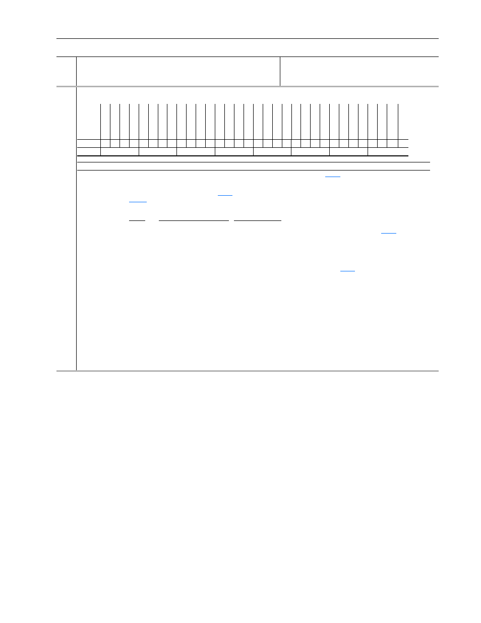
Control Options
Set bits to configure the options for operating the drive.
No.
Name
Description
Values
Li
nkab
le
Read
-Wr
it
e
Da
ta
T
ype
Options
Re
se
rv
ed
Re
se
rv
ed
Re
se
rv
ed
Re
se
rv
ed
Re
se
rv
ed
Tr
q T
ri
m
E
n
Re
se
rv
ed
Re
se
rv
ed
Re
se
rv
ed
Re
se
rv
ed
Re
se
rv
ed
Re
se
rv
ed
Re
se
rv
ed
Re
se
rv
ed
A
ux Pwr
Sp
ly
A
uto
T
ac
h
Sw
Re
se
rv
ed
Re
se
rv
ed
OL
Cl
sL
pDsb
l
Jog -N
oIn
teg
Iq
De
la
y
Mo
tor Dir
2W
C
oas
tS
to
p
3W
ireCon
tr
ol
S
top
Cn
dt
Tq
St
op
in
T
orq
Jog - NoR
amp
Jog in
Torq
2W
Cu
rr
Li
m
S
tp
S
reg
LP
F 1
S
Ref Filt En
B
ipo
la
r SRef
Default
0
0
0
0
0
0
0
0
0
0
0
0
0
0
0
0
0
0
0
0
0
0
0
1
0
0
0
0
0
0
0
1
Bit
31 30 29 28 27 26 25 24 23 22 21 20 19 18 17 16 15 14 13 12 11 10 9
8
7
6
5
4
3
2
1
0
Bit
Name
Current Function
0
Bipolar SRef
When this bit is enabled a bipolar speed reference is used. In bipolar reference mode,
[Selected Spd Ref] indicates both the
speed magnitude and the direction: Positive speed reference values (+) = forward direction and negative speed reference values (–)
= reverse direction. When this bit is disabled a unipolar speed reference is used. In unipolar mode, the speed reference is limited to a
minimum value of zero (0). In this case
[Selected Spd Ref] supplies only the speed magnitude. The direction is determined by
[Applied LogicCmd] bits 20 [UniPol Fwd] and 21 [UniPol Rev]. The forward/reverse direction button on the HIM is one
possible source for the [Applied Logic Command] direction bits. The following chart explains the effect that the direction button on the
HIM has based on the condition of the “Bipolar SRef” bit:
Bipolar
Reference Controlled By HIM? HIM Direction Button
Enabled
Yes
Changes the motor direction due to a HIM supplied (+) or (-) command signal
Enabled
No
Has no effect on motor direction. Direction determined by sign of
[Selected Spd
Ref].
Disabled
Yes
Changes the motor direction due to a HIM supplied Forward or Reverse Logic
Command bit.
Disabled
No
Changes the motor direction due to a HIM supplied Forward or Reverse Logic
Command bit.
In either Bipolar or Unipolar mode, the selected direction can be determined from the sign of
[Limited Spd Ref]. Positive
values indicate forward rotation and negative values indicate reverse rotation.
1
SRef Filt En
Enables Speed Reference Lead Lag Filter-reset disables
2
Sreg LPF 1
Setting this bit will enable the speed regulator filter as a single order low pass filter
4
Jog in Torq
Overrides Par 110 [Spd/Torq ModeSel] setting when jog command received
5
Jog-NoRamp
Bypasses the Speed Reference Ramp and S-Curve
6
Stop in Torq
Overrides Par 110 [Spd/Torq ModeSel] setting when stopping
8
3WireControl
Configures for 3-wire control
11
Iq Delay
Enables Torque Current Delay option
12
Jog-NoInteg
Configures speed regulator’s integrator to hold when jogging
17
Aux Pwr Sply
Enables use of Aux. Power Supply. When set to 1, Main Control Board examines internal 12V DC power to see when energized.
When set to 0, examines voltage of DC Bus. This bit enables Main Control Board and DriveLogix Controller to remain energized
when 3-Ø voltage is de-energized.
0 = False
1 = True