Figure 1.2, 10 installation/wiring, Phase selection jumper fan voltage – Rockwell Automation 20D PowerFlex 700S Drive Ph I Control, Frames 1...11 User Manual
Page 24
1-10
Installation/Wiring
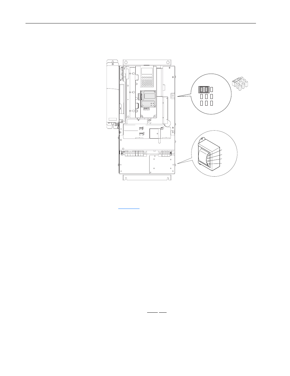
Figure 1.2 Frames 5 & 6 Jumper and Transformer Locations (Frame 5 shown)
Frame 6 Transformer Tap Access
The transformer is located behind the Power Terminal Block in the area
shown in
. Gain access by releasing the terminal block from the
rail. To release terminal block and change tap:
1. Locate the small metal tab at the bottom of the end block.
2. Press the tab in and pull the top of the block out. Repeat for next block if
desired.
3. Select appropriate transformer tap.
4. Replace block(s) in reverse order.
Important Common Bus (DC Input) Application Notes
1. If drives without internal precharge are used (Frames 5 & 6 only), then:
a) precharge capability must be provided in the system to guard against
possible damage, and
2. disconnect switches Must Not be used between the input of the drive and
a common DC bus without the use of an external precharge device.
WIRE RANGE: 14-1/0 AWG (2.5-35 MM
2
)
TORQUE: 32 IN-LB (3.6 N-M)
STRIP LENGTH: 0.67 IN (17 MM)
USE 75 C CU WIRE ONLY
POWER TERMINAL RATINGS
WIRE RANGE: 6-1/0 AWG (16-35 MM
2
)
TORQUE: 44 IN-LB (5 N-M)
STRIP LENGTH: 0.83 IN (21 MM)
GROUND TERMINAL RATINGS (PE)
300 VDC EXT PWR SPLY TERM (PS+, PS-)
WIRE RANGE: 22-10 AWG (0.5-4 MM
2
)
TORQUE: 5.3 IN-LB (0.6 N-M)
STRIP LENGTH: 0.35 IN (9 MM)
17
21
INPUT AC
OUTPUT
Optional
Communications
Module
9
LINE
TYPE
SPARE 1
SPARE 2
3-PH 1-PH
480 Volt Tap
600 Volt Tap
690 Volt Tap
400 Volt Tap
Phase Selection
Jumper
Fan Voltage