Table 1.q tb2 - row b (bottom) wiring examples – Rockwell Automation 20D PowerFlex 700S Drive Ph I Control, Frames 1...11 User Manual
Page 45
Installation/Wiring
1-31
Table 1.Q TB2 - Row B (Bottom) Wiring Examples
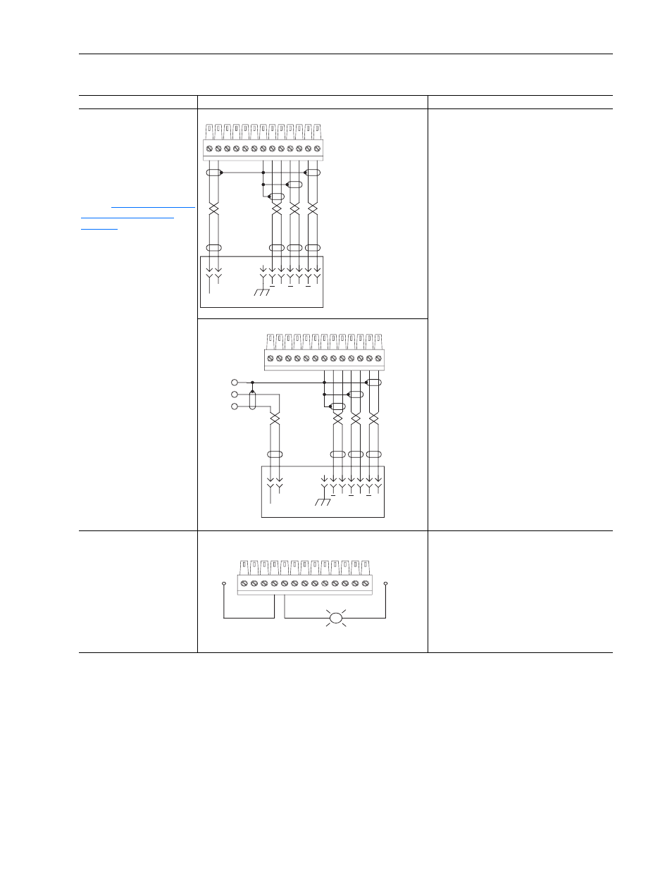
Input/Output
Connection Example
Required Parameter Changes
Secondary Encoder Interface
- Supports 12V DC differential
encoders with internal power
supply.
5V DC differential encoders
require external power supply
and special jumper settings.
Refer to
Configuration Settings on
page 1-32
for external power
supply and jumper settings.
For 5V DC differential encoders
with internal power supply, set
Jumper J6 to positions T2 and
T3.
Secondary Encoder - using internal power supply
• Set the value of Parameter 222 [Motor Fdbk
Sel] to a value of 1 - Encoder 1, so the drive will
use this encoder as the primary motor speed
feedback device
• Set the value of Parameter 242 [Encoder1 PPR]
to match the encoder’s resolution
Secondary Encoder - using external power supply
Auxiliary Output - Relay
contact output
Auxiliary Output, Used to Indicate Running
• Link Parameter 155 [Logic Status], the source,
to Parameter 841 [Relay Out Data], the sink
• Set Parameter 842 [Relay Out Bit] to a value of
one, so that Parameter 155 [Logic Status] / bit 1
“Running” will control the output.
13
12
11
10
9
8
7
2
1
Power
Common
(Return)
A
A
B
B
Z
Z
Case Ground
13
12
11
10
9
8
7
Power
Common
(Return)
A
A
B
B
Z
Z
Case Ground
Shield
Power
Common
(Return)
4
5
Running
EXTERNAL 24V
POWER SUPPLY
EXTERNAL
24V DC
COMMON
(RETURN)