Wiring the main control board i/o terminals, Auxiliary power supply – Rockwell Automation 20D PowerFlex 700S Drive Ph I Control, Frames 1...11 User Manual
Page 34
1-20
Installation/Wiring
Wiring the Main Control Board I/O Terminals
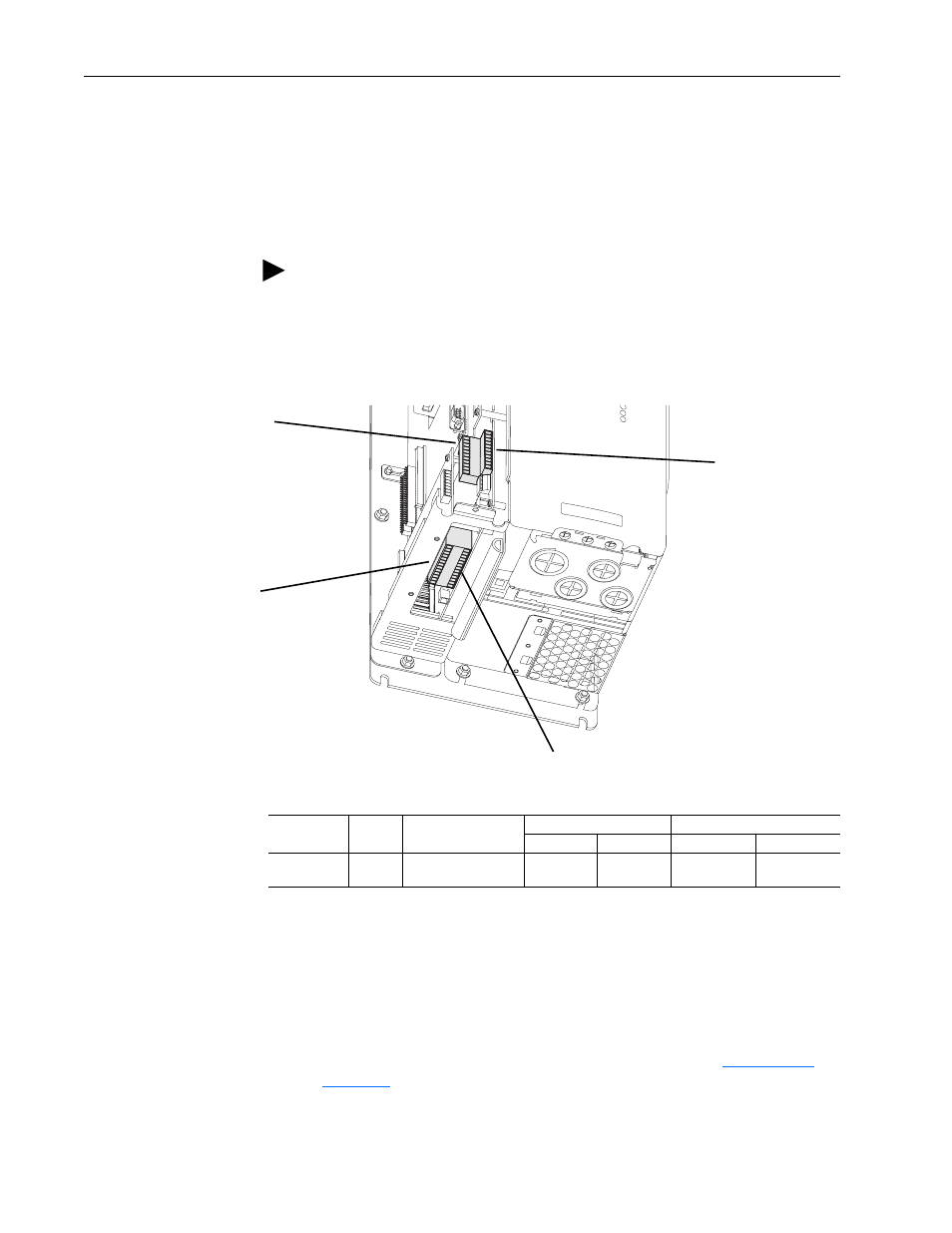
Terminal blocks TB1 and TB2 contain connection points for all inputs,
outputs and standard encoder connections. Both terminal blocks reside on
the Main Control Board.
Remove the terminal block plug from the socket, and make connections.
Reinstall the plug, when wiring is complete. The terminal blocks have keys,
which make it difficult to insert a terminal plug into the wrong socket.
Table 1.H Main Control Board I/O Terminal Locations
Table 1.I Main Control Board I/O Terminal Block Specifications
Auxiliary Power Supply
You may use an auxiliary power supply to keep the 700S Control Assembly
energized when output power is de-energized. This allows the Main Control
Board, DriveLogix controller and any feedback option cards to continue
operation. Connect auxiliary power to terminal block. See
. You must set Par 153 [Control Options], bit 7 [Aux Pwr Sply] to
enable this feature.
TIP: Remember to route wires through the sliding access panel at the
bottom Control Assembly.
TB1
TB2
TB1 - Row T (Top)
TB1 - Row B (Bottom)
TB2 - Row T (Top)
TB2 - Row B (Bottom)
Name
Frame
Description
Wires Size Range
(1)
Torque
Maximum
Minimum
Maximum
Recommended
I/O & Encoder
Blocks
1-6
Signal & Encoder
power connections
1.5 mm
2
(16 AWG)
.14 mm
2
(28 AWG)
.25 N-m
(2.2 lb.-in.)
.22 N-m
(1.9 lb.-in.)
(1)
Maximum/minimum sizes the terminal block will accepts - these are not recommendations.