Rockwell Automation 20D PowerFlex 700S Drive Ph I Control, Frames 1...11 User Manual
Page 108
3-54
Programming and Parameters
No.
Name
Description
Values
Li
nk
ab
le
R
ead-
Wri
te
D
ata
T
ype
411
PreChrg Control
Must equal 1 “Enbl PrChrg” to allow the drive to exit precharge and begin to run. Link this
parameter to a controller output word to coordinate the precharge of multiple drives.
Default:
Options:
1
0
1
“Enbl PrChrg”
“Hold PrChrg”
“Enbl PrChrg”
412
Power EE TP Sel
Enter or write a value to select drive power EEPROM data displayed in Par 413 [Power
EE TP Data].
Default:
0
Zero
413
Power EE TP Data
Displays the data selected by Par 412 [Power EE TP Sel].
Default:
Min/Max:
0
-/+2200000000
Real
414
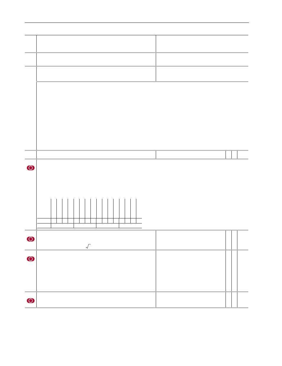
Brake/Bus Cnfg
Configures the brake and bus operation of the drive.
• Set bit 0 [Brake Enable] to enable the operation of the internal brake transistor.
• Set bit 1 [Brake Extern] to configure the brake to use an external resistor.
• Set bit 2 [BusRef High] to select the "high" voltage setting as the turn-on point for the Bus Voltage Regulator. The "high" setting brake operation starts when
bus voltage reaches the value of Par 415 [BusReg/Brake Ref], and the Bus Voltage Regulator operation starts when bus voltage reaches the value of 415
[BusReg/Brake Ref] plus 4.5%. With the "low" setting both brake and regulator operation start when bus voltage reaches the value of 415 [BusReg/Brake
Ref].
• Set bit 3 [Bus Reg En] to enable the Bus Voltage Regulator. The output of the Bus Voltage Regulator is summed with Par 128 [Regen Power Lim] and fed
into the Power Limit Calculator. It, in effect, reduces negative torque references when the bus voltage is too high.
415
BusReg/Brake Ref
Sets the “turn-on” voltage for the bus regulator and brakes. Enter a percentage of the
high voltage setting for the voltage class. For example, on a 400-480V drive:
Units:
Default:
Min/Max:
%
111.0000
110.5000117.8000
✓ Real
416
Brake PulseWatts
Limits the power delivered to the external Dynamic Brake (DB) resistor for one second,
without exceeding the rated element temperature. You may change the value of this
parameter only if you have selected an external DB resistor (set bit 1 [Brake Extern] of
Par 414 [Brake/Bus Cnfg]). If this rating is not available from the resistor vendor, you can
approximate it with this equation: Par 416 [Brake PulseWatts] = 75,000 x Weight, where
Weight equals the weight of the resistor wire element in pounds (not the entire weight of
the resistor). Another equation you can use is: Par 416 [Brake PulseWatts] = Time
Constant x Brake Watts; where Time Constant equals the amount of time to reach 63% of
its rated temperature the maximum power applied, and Brake Watts is the maximum
power rating of the resistor.
Units:
Default:
Min/Max:
Watt
2000.0000
1.0000/1000000.0000
✓ Real
417
Brake Watts
Sets the maximum continuous power reference for the Dynamic Brake (DB). You may
change the value of this parameter only if you have selected and external DB resistor (set
bit 1 [Brake Extern] of Par 414 [Brake/Bus Cnfg]).
Units:
Default:
Min/Max:
Watt
100.0000
0.0000/5000.0000
✓ Real
Options:
0 Zero
12 Mw Hrs Accum 24 Inv Rated Kw
36 IGBTs per Pk 48 Diode JC Tr
60 DB Ambt Tmax 72 Mtr IR Vdrop 84 Mtr IR Vdrop
1 Volt Class
13 Inv High Vlt
25 Inv Rated V
37 GBT Rated V 49 Diode JC Tc
61 Convt Type
73 Mtr Id Ref
85 Mtr Id Ref
2 Assy Rev
14 Reserved
26 Inv Rated A
38 IGBT Rated A 50 GBT Tjmax
62 DC Bus Induc 74 HH Data Rev 86 HH Extr Data
3 ASA S/N
15 Fan/Pwr Cntl
27 Inv 1min Amp
39 IGBT V Thres 51 HS Max DegC 63 AC Inp Induc
75 HH Dev Type 87 HH Volt Indx
4 Manuf Year
16 Temp Sensor
28 inv 3sec Amp
40 IGBT Slope R 52 DB IGBT Amp 64 Precharg Res 76 HH Serial #
88 HH Size Indx
5 Manuf Month 17 Phs AmpScale 29 SW OverC Amp 41 IGBT Sw Engy 53 DB ohms
65 PrechThrm Tc 77 HH Test Date 89 HH Option
6 Manuf Day
18 Gnd AmpScale 30 DC Bus Cap
42 IGBT JC Tres 54 DB E Jo/degC 66 Mtr NP Units
78 HH Vcn Code 90 HH Hrd Prdct
7 Tst ProcStat 19 Bus VltScale
31 Min PWM Khz 43 IGBT JC Tc
55 DB EB C/Wat 67 Mtr NP Power 79 HH CrsCnc ID 91 HH H/W Mdfy
8 Life PwrCycl 20 Sml PS Watts 32 Max PWM Khz 44 IGBT CS Tres 56 DB B Jo/degC 68 Mtr NP Volts
80 HH P/B ID
92 HH 1V/Amp
9 Life Pwrup
21 Sml PS Min V 33 Dfl PWM Khz
45 IGBT CS Tc
57 DB BA C/Watt 69 Mtr NP Amps 81 HH S/W ID
93 HH 2s/Amp
10 Life RunTime 22 Lrg PS Watts
34 PWM Dead us 46 Diode V Thrs 58 DB Elem Tmax 70 Mtr NP Freq
82 HH P/B Rev
94 HH Scale
11 Kw Accum
23 Lrg PS Min V
35 Drive Frame
47 Diode SlopeR 59 DB Body Tmax 71 Mtr NP RPM
83 HH S/W Rev
Options
Rese
rv
ed
Rese
rv
ed
Rese
rv
ed
Rese
rv
ed
Rese
rv
ed
Rese
rv
ed
Rese
rv
ed
Rese
rv
ed
Rese
rv
ed
Rese
rv
ed
Rese
rv
ed
Rese
rv
ed
Bus Reg En
Bus Ref
H
ig
h
Br
ak
e Ext
er
n
Br
ak
e Enab
le
Default
0
0
1
1
0
0
0
0
0
0
0
0
0
0
0
0
Bit
15 14 13 12 11 10 9
8
7
6
5
4
3
2
1
0
0 = False
1 = True
111
2
×
480
VDC
=
Ч