Rockwell Automation 20D PowerFlex 700S Drive Ph I Control, Frames 1...11 User Manual
Page 137
Programming and Parameters
3-83
No.
Name
Description
Values
Li
nk
ab
le
R
ead-
Wri
te
D
ata
T
ype
1024
SL Tx DirectSel3
Determines the source type for the data transmitted by direct transmit word 3. The source
type selections are: no data, event, feedback and drive parameter. If drive parameter is
selected, a parameter of the appropriate data format (integer or real) must be linked to Par
1147 [SL Dir Int Tx3] or Par 1148 [SL Dir Real Tx3]. Configure the selection by using the
Peer Communication window in the DriveExecutive programming software.
Default:
Options:
0
0
1
2
3
4
5
6
7
8
9
10
11
12
13
“No Data”
“No Data”
14 “Reserved”
“SL Multiply”
15 “Reserved”
“Event P0”
16 “Reserved”
“Event P1”
17 “Reserved”
“Reserved”
18 “Reserved”
“Reserved”
19 “Reserved”
“Reserved”
20 “Reserved”
“Reserved”
21 “Dir Tx Data”
“Event Opt0”
22 “Dir Rx Data”
“Reserved”
23 “E0 Accum”
“Event Status”
24 “E1 Accum”
“Reserved”
25 “Opt0 Accum”
“Reserved”
26 “Opt1 Accum”
“Reserved”
1030
SL Mult A In
Displays the A Multiplier Input, as a floating point (real) value. This value is divided by the
Par 1032 [SL Mult Base]. The source of the A Multiplier is determined by the "Rx Direct
Data Selector" (Pars 1011-1014). The possible sources are: 0 (zero), Par 1054 [SL Dir Int
Rx0], Par 1056 [SL Dir Int Rx1], Par 1058 [SL Dir Int Rx2], or Par 1060 [SL Dir Int Rx3].
The SynchLink Multiply function takes this input before it is converted to floating point.
Default:
Min/Max:
0.0000
0.0000/65535.0000
Real
1031
SL Mult B In
The B Multiplier Input. This must be a floating point (real) value. The SynchLink Multiply
function takes this input after it is converted to integer.
Default:
Min/Max:
1.0000
0.25000/2.0000
✓ ✓ Real
1032
SL Mult Base
Specifies the base for SynchLink real to integer and integer to real conversion functions.
Determines the resolution of the conversion results. You must use the same value at the
transmitting node and receiving / multiplying nodes. Enter a value that will not produce an
overflow - the product of this value and the inputs to the conversion and multiply functions
must be less than 65,536.
Default:
Min/Max:
10000.0000
0.2000/50000.0000
✓ Real
1033
SL Mult Out
Displays the output of the SynchLink Multiply function as a floating (real) value. The value
is the result of the formula Par 1030 [SL Mult A In] source (integer) x Par 1031 [SL Mult B
In] / Par 1032 [SL Mult Base] or Par 1030 [SL Mult A In] x Par 1031 [SL Mult B In]. Note:
the SynchLink Multiply function produces an output that is always positive.
Default:
Min/Max:
0.0000
0.0000/65535.0000
Real
1034
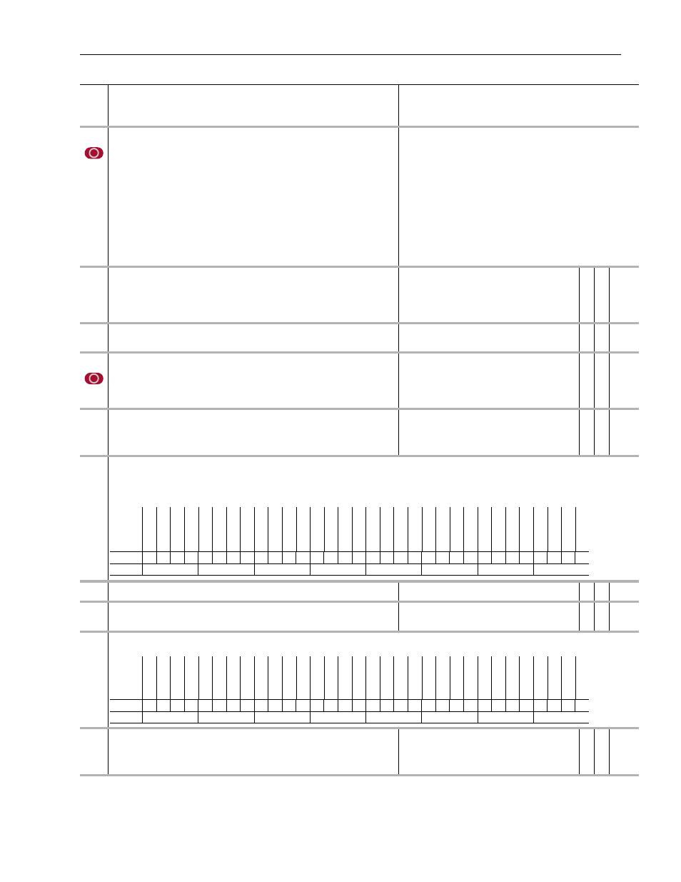
SL Mult State
Displays the status of the SynchLink Multiply function.
• Bit 0 [Local Ovflow] indicates a math overflow due to local multiply.
• Bit 1 [Rx Overflow] indicates a math overflow in received data.
• Bit 3 [Ftol Ovflow] indicates a math overflow in the real to integer conversion function.
1035
Real to Int In
Provides the floating point (real) input to the real to integer conversion function.
Default:
Min/Max:
0.0000
-/+16.0000
✓ v Real
1036
Real to Int Out
Displays the integer output of the real to integer conversion function. The value is the
result of the formula Par 1035 [Real to Int In] x Par 1032 [SL Mult Base].
Default:
Min/Max:
0
0/65535
16-bit
Integer
1040
SL Rcv Events
Displays the received event status from Par 1041 [SL Rx P0 Regis] through Par 1047 [SL Rx Opt0 Regis].
1041
SL Rx P0 Regis
Displays received port 0 registration data, if direct received data is configured to be port 0
registration data by the Rx Direct Data Selector (Pars 1011-1014). Configure this
selection by using the Peer Communication window in the DriveExecutive programming
software.
Default:
Min/Max:
0
-/+2147483648
32-bit
Integer
Options
Rese
rv
ed
Rese
rv
ed
Rese
rv
ed
Rese
rv
ed
Rese
rv
ed
Rese
rv
ed
Rese
rv
ed
Rese
rv
ed
Rese
rv
ed
Rese
rv
ed
Rese
rv
ed
Rese
rv
ed
Rese
rv
ed
Rese
rv
ed
Rese
rv
ed
Rese
rv
ed
Rese
rv
ed
Rese
rv
ed
Rese
rv
ed
Rese
rv
ed
Rese
rv
ed
Rese
rv
ed
Rese
rv
ed
Rese
rv
ed
Rese
rv
ed
Rese
rv
ed
Rese
rv
ed
Rese
rv
ed
Ft
oI Ovf
lo
w
Rese
rv
ed
Rx
Ov
flow
Loc
al Ovf
lo
w
Default
0
0
0
0
0
0
0
0
0
0
0
0
0
0
0
0
0
0
0
0
0
0
0
0
0
0
0
0
0
0
0
0
Bit
31 30 29 28 27 26 25 24 23 22 21 20 19 18 17 16 15 14 13 12 11 10 9
8
7
6
5
4
3
2
1
0
0 = False
1 = True
Options
Rese
rv
ed
Rese
rv
ed
Rese
rv
ed
Rese
rv
ed
Rese
rv
ed
Rese
rv
ed
Rese
rv
ed
Rese
rv
ed
Rese
rv
ed
Rese
rv
ed
Rese
rv
ed
Rese
rv
ed
Rese
rv
ed
Rese
rv
ed
Rese
rv
ed
Rese
rv
ed
Rese
rv
ed
Rese
rv
ed
Rese
rv
ed
Rese
rv
ed
Rese
rv
ed
Rese
rv
ed
Rese
rv
ed
Rese
rv
ed
Rese
rv
ed
Opt0
Re
gi
s
Rese
rv
ed
Rese
rv
ed
Rese
rv
ed
D0Res
er
ved
E1 Regis
E0 Regis
Default
0
0
0
0
0
0
0
0
0
0
0
0
0
0
0
0
0
0
0
0
0
0
0
0
0
0
0
0
0
0
0
0
Bit
31 30 29 28 27 26 25 24 23 22 21 20 19 18 17 16 15 14 13 12 11 10 9
8
7
6
5
4
3
2
1
0
0 = False
1 = True