Rockwell Automation 20D PowerFlex 700S Drive Ph I Control, Frames 1...11 User Manual
Page 39
Installation/Wiring
1-25
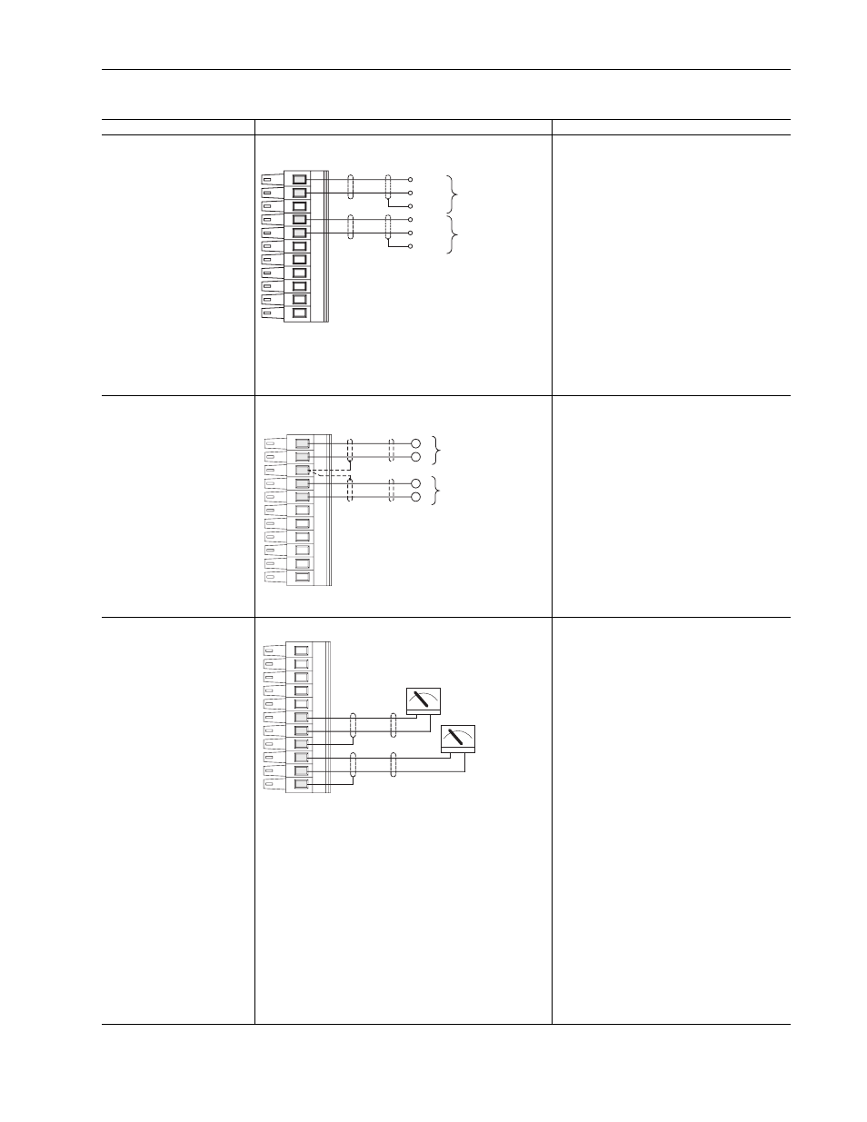
Table 1.M TB1 - Row B (Bottom) Wiring Examples
Input/Output
Connection Example
Required Parameter Changes
Analog Inputs
+/-10V DC or +/-1.0V DC
(DIP switch selectable)
Terminate shields at the analog
source if analog common is
available
Used for Speed Reference and
Speed Trim
Analog Inputs for Speed Reference and Speed Trim - shield
terminated at source
Using Analog In1 as 0-10V speed reference
• Adjust Parameter 803 [Anlg In1 Offset] so that
the minimum analog signal creates the minimum
speed reference (if the minimum input is 0V DC
and the minimum speed reference is zero, enter
a value of zero)
• Adjust the Parameter 802 [Anlg In1 Scale] so
that the maximum analog signal creates the
maximum speed reference (if the maximum
input is 10V DC and the maximum speed
reference is motor base speed, enter a value of
0.1)
• Send the data to the Speed Reference
parameter
Par 10 [Speed Ref 1] (the destination) linked to
Par 800 [Anlg In1 Data] (the source)
• Select Ref 1 as the active speed ref Par 16
[Speed Ref Sel] = 1
• Par 153 [Control Options], bit 0 = 0 Unipolar
Speed Reference”
Analog Outputs
+/-10V DC or +/-1.0V DC
Used to drive analog meters
displaying speed and current
Analog Inputs for Speed Reference and Speed Trim - shield
terminated at drive
Using Analog In2 as -10 to +10V speed trim @
10%:
• Adjust Parameter 809 [Anlg In2 Offset] so that
the minimum analog signal creates the minimum
speed trim (if the minimum input is 0V DC and
the minimum trim is zero, enter a value of zero)
• Adjust Parameter 808 [Anlg In2 Scale] so that
the maximum analog signal creates the
maximum speed trim (if the maximum input is
10V DC and the maximum speed trim is 10%,
enter a value of 0.01)
• Send the data to the speed Reference
parameter
Par 12 [Speed Ref 2] (the destination) linked to
Par 806 [Anlg In2 Data] (the source)
• Select Ref 1 as the active speed ref and Ref 2
as trim [Speed Ref Sel] = 3
Analog Outputs
+/-10V DC
Analog Outputs Indicating Motor Speed and Motor Current
Using Analog Out 1, -10V to +10V to meter
Motor RPM and direction:
• Adjust Parameter 812 [Anlg Out1 Offset] so that
minimum speed creates a minimum signal (if the
minimum speed is zero and the minimum signal
is zero, enter a zero)
• Adjust Parameter 817 [Anlg Out1 Scale] so that
the maximum speed creates a maximum signal
(if the maximum speed is 100% of motor base
speed and the maximum signal is 10V DC, enter
a value of 0.1)
• Send the data to the Analog Output
Par 815 [Anlg Out1 Real] (the destination) linked
to Par 300 [Motor Spd Fdbk] (the source)
Using Analog Out 2, -10V to +10V to meter
Motor Current
• Adjust Parameter 813 [Anlg Out2 Offset] so that
minimum current creates a minimum signal (if
the minimum current is zero and the minimum
signal is zero, enter a zero)
• Adjust Parameter 822 [Anlg Out2 Scale] so that
the maximum current creates a maximum signal
(if the maximum current is 200% of motor NP
FLA and the maximum signal is 10V DC, enter a
value of 2.0)
• Send the data to the Analog Output
Par 820 [Anlg Out2 Real] (the destination) linked
to Par 308 [Output Current] (the source)
• Scale the Output to the source parameter
Par 822 [Anlg Out2 Scale] = xx (Par2 [Motor NP
FLA]/10V Output
11
10
8
7
-
+
Common
(Return)
Analog Input #1
Speed
Reference
-
+
Common
(Return)
Analog Input #2
Speed
Trim
11
10
8
7
-
+
-
+
9
Speed Reference
0-10V dc = 0-100%
of Motor Base Speed
Speed Trim
0-10V dc = 0-10%
Trim
+
-
+
-
2
3
4
5
6
1
Output #1
Motor
Speed
Output #2
Motor
Current