Rockwell Automation 20D PowerFlex 700S Drive Ph I Control, Frames 1...11 User Manual
Page 78
3-24
Programming and Parameters
140
FricComp Spd Ref
Supplies a speed input to the Friction Compensation algorithm. This input is normally a
speed reference from a motion planner or ramped speed reference. It will trigger a torque
feed forward response depending on its value.
Units:
Default:
Min/Max:
Comm Scale:
RPM
0.0000
-/+14112.0000
Par 4 [Motor NP RPM] = 1.0
✓ ✓ Real
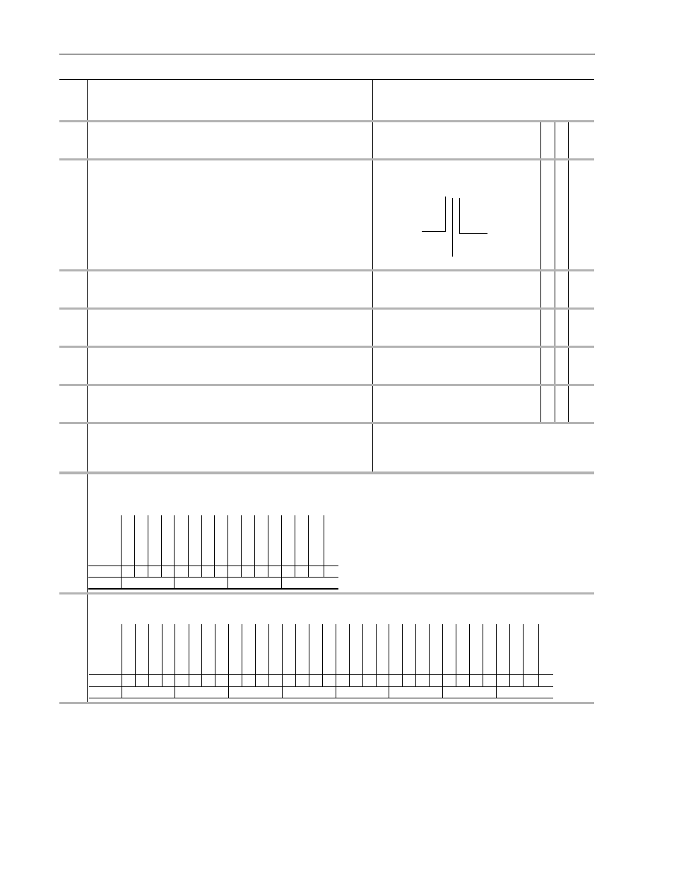
141
FricComp Setup
Enter or write a value to configure the friction compensation algorithm. This is a packed
word of 3 digits. Each digit has a possible selection of 10 levels.
• The least significant digit sets the speed threshold in intervals of 0.0005 pu speed.
• The next (middle) digit sets the hysteresis band for the “units” digit in intervals of
0.0005 pu velocity.
• The most significant digit sets the number of time steps from stick to slip, each step is
0.002 sec.
Example: Fsetup = 524 means, 5 time steps between stick and slip, each of 0.002 sec.
duration, 2 counts of hysteresis or 0.001 pu_speed (each count is 0.0005 pu speed), and
4 counts or 0.002 pu_speed is the trigger threshold (each count is 0.0005 pu speed).
Default:
Min/Max:
325
0/999Integer
✓ 16-bit
Integer
142
FricComp Stick
The torque needed to break away from zero speed. By the nature of friction, the break
away sticktion will always be greater than the running friction.
Units:
Default:
Min/Max:
Comm Scale:
P.U.
0.1500
0.0000/8.0000
Motor P.U. Torque
✓ ✓ Real
143
FricComp Slip
The torque level to sustain very low speed – once “break away” has been achieved. By
the nature of friction, viscous friction will always be less than sticktion.
Units:
Default:
Min/Max:
Comm Scale:
P.U.
0.1000
0.0000/8.0000
Motor P.U. Torque
✓ ✓ Real
144
FricComp Rated
The torque needed to a base friction at base motor speed and with no process loading.
The friction compensation algorithm assumes a linear or viscous component of friction
between Par 143 [FricComp Slip] and Par 144 [FricComp Rated].
Units:
Default:
Min/Max:
Comm Scale:
P.U.
0.2000
0.0000/8.0000
Motor P.U. Torque
✓ ✓ Real
145
FricComp TorqAdd
The torque reference output of the Friction Compensation function. A value of 1.0
represents rated torque of the motor.
Units:
Default:
Min/Max:
Comm Scale:
P.U.
0.0000
-/+8.0000
Motor P.U. Torque
Real
150
Logic State Mach
Indicates the logical state of the drive.
Value 0 - “Stopped” indicates zero speed has been detected and the speed and torque
regulators are disabled.
Default:
Options:
0
0
1
2
3
“Stopped”
“Stopped”
4
“Inertia Test”
“Starting”
5
“MC Diag”
“Running”
6
“Test Done”
“Stopping”
151
Logic Command
The controller-drive interface (as defined by the Controller Communication Format) sets bits to enable and disable various functions and algorithms. Bits that
are changed here are reflected in Par 152 [Applied LogicCmd]. Note: Bits 4 through 9 in Logic Command are NOT recalled from Control EEprom. They will be
cleared upon drive power up or following an EEprom recall operation.
152
Applied LogicCmd
Displays Logic Command that is applied to the Regulators and Control Algorithms within the drive. Logic Commands come from the 32-bit Logic Command
found in a connection with the Logix Controller.
No.
Name
Description
Values
Li
nkab
le
Read
-Wr
it
e
Da
ta
T
ype
N N N
Units
Hysteresis
Number of
Time Steps
Options
Rese
rv
ed
Rese
rv
ed
P
os
itionEn
bl
ProcsT
ri
m En
Fr
ic
t C
om
p
In
er
tia
Co
mp
Sys
Iner
t En
Mt
r I
ner
t En
PM Offs
et
En
Dir Sel En
Pwr Diag
En
MC A
tun
e
En
Time Axis En
Tac
hLos
s Rst
Spd S Cr
v En
SpdRa
m
p Dsb
l
Default
0
0
0
0
0
0
0
0
0
0
0
0
0
0
0
0
Bit
15 14 13 12 11 10 9
8
7
6
5
4
3
2
1
0
0 = False
1 = True
Options
Rese
rv
ed
Rese
rv
ed
Rese
rv
ed
Rese
rv
ed
Rese
rv
ed
Rese
rv
ed
Coas
t St
op
CurrL
im Stop
Jog
2
Rese
rv
ed
UniP
ol
Re
v
UniP
ol
Fwd
Clear
F
ault
Jog
1
Star
t
Nor
m
al Stop
Rese
rv
ed
Rese
rv
ed
P
os
itionEn
bl
ProcsT
ri
m En
Fr
ic
t C
om
p
In
er
tia
Co
mp
Sys
Iner
t En
Mt
r I
ner
t En
PM Offs
et
En
Dir Sel En
Pwr Diag
En
MC A
tun
e
En
Time Axis En
Tac
hLos
s Rst
Spd S Cr
v En
SpdRa
m
p Dsb
l
Default
0
1
0
1
1
0
0
0
0
1
0
0
0
0
1
0
0
0
0
0
0
0
0
0
0
0
0
0
0
0
0
0
Bit
31 30 29 28 27 26 25 24 23 22 21 20 19 18 17 16 15 14 13 12 11 10 9
8
7
6
5
4
3
2
1
0
0 = False
1 = True