Allied Telesis AT-S63 User Manual
Page 285
AT-S63 Management Software Menus Interface User’s Guide
Section II: Advanced Features
285
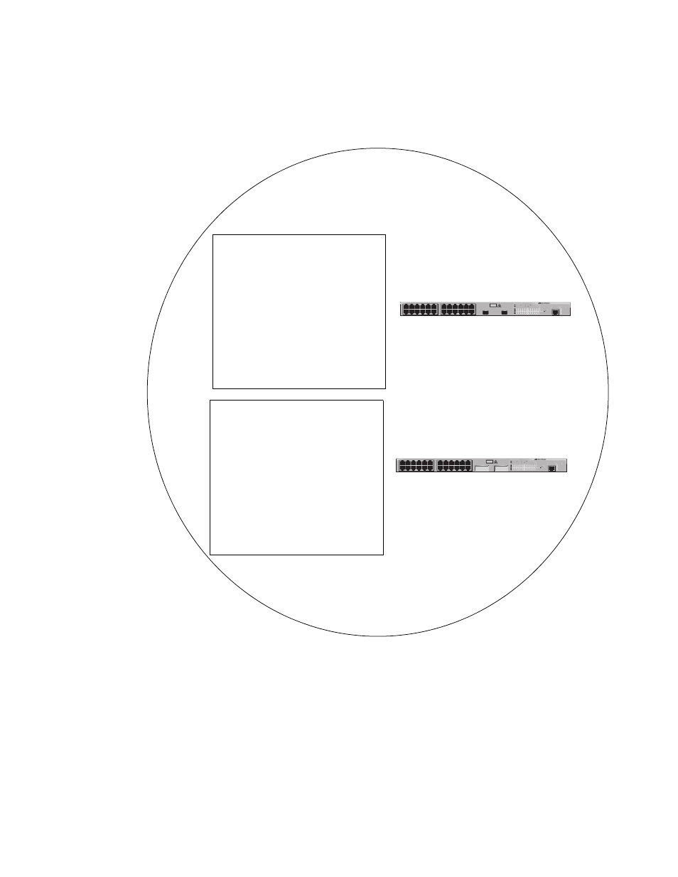
Figure 91 illustrates the concept of regions. It shows one MSTP region
consisting of two AT-9400 Series switches. Each switch in the region has
the same configuration name and revision level. The switches also have
the same five VLANs and the VLANs are associated with the same MSTIs.
Figure 91. Multiple Spanning Tree Region
The AT-9400 Series switch determines regional boundaries by
examining the MSTP BPDUs received on the ports. A port that receives a
MSTP BPDU from another bridge with regional information different
from its own is considered to be a boundary port and the bridge
connected to the port as belonging to another region.
FAULT
RPS
MASTER
POWER
GBIC
23
GBIC
24
CLASS 1
LASER PRODUCT
STATUS
TERMINAL
PORT
1
3
5
7
9
11
2
4
6
8
10
12
13
15
17
19
21
23R
14
16
18
20
22
24R
AT-9424T/GB
Gigabit Ethernet Switch
1
3
5
7
9
11
13
15
17
19
21
23R
2
4
6
8
10
12
14
16
18
20
22
24R
23
24
L/A
D/C
D/C
L/A
D/C
L/A
1000 LINK / ACT
HDX / COL
FDX
10/100 LINK / ACT
PORT ACTIVITY
L/A
1000 LINK / ACT
GBIC
Configuration Name:
Marketing Region
Revision Level: 1
VLAN to MSTI Associations:
MSTI ID 1
VLAN: Sales (VID 2)
VLAN: Presales (VID 3)
Configuration Name:
Marketing Region
Revision Level: 1
VLAN to MSTI Associations:
MSTI ID 1
VLAN: Sales (VID 2)
VLAN: Presales (VID 3)
FAULT
RPS
MASTER
POWER
CLASS 1
LASER PRODUCT
STATUS
TERMINAL
PORT
1
3
5
7
9
11
2
4
6
8
10
12
13
15
17
19
21
23R
14
16
18
20
22
24R
AT-9424T/SP
Gigabit Ethernet Switch
1
3
5
7
9
11
13
15
17
19
21
23R
2
4
6
8
10
12
14
16
18
20
22
24R
23
24
L/A
D/C
D/C
L/A
D/C
L/A
1000 LINK / ACT
HDX / COL
FDX
10/100 LINK / ACT
PORT ACTIVITY
L/A
1000 LINK / ACT
SFP
SFP
24
SFP
23