Allied Telesis AT-S63 User Manual
Page 147
AT-S63 Management Software Menus Interface User’s Guide
Section I: Basic Features
147
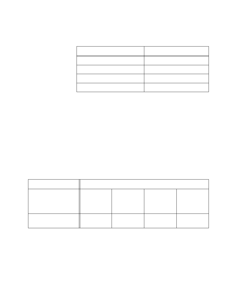
Table 2 shows how switch #2 might distribute the server traffic across
the ports of the trunk using the destination MAC address method.
For example, when the server connected to switch #2 needs to send a
packet to workstation C, the switch uses port 15.
Source Address/Destination Address Distribution Methods
With this distribution method, a switch creates a matrix of the source
and destination addresses and then uses the matrix to determine which
port in the trunk a frame is to be transmitted. With this method, packets
from a particular source node might be sent over different data links in a
trunk when sent to different destination addresses.
As an example of how this works, assume that you configured switch #2
in the example with source MAC address/destination MAC address. The
result might be something similar to that shown in Table 3.
Even though there is only one source, all the data links in the trunk are
used. For instance, if the server needs to send a packet to workstation C,
by referring to the matrix switch #2 would use port 3 of the trunk to
transmit the packet from that particular source MAC address to switch
#1.
Table 2. Switch #2 - Destination MAC Address Load Distribution
Method
Destination Address
Trunk Port
Workstation A - 00A0EE 2313A3
13
Workstation B - 00A134 1A9032
15
Workstation C - 00A301 9083B2
15
Workstation D - 001B21 87C6D6
17
Table 3. Switch #2 - Source MAC Address/Destination MAC Address Method
Destinations MAC Addresses
Source MAC Address
Workstation
A
00A0EE
2313A3
Workstation
B
00A134
1A9032
Workstation
C
00A301
9083B2
Workstation
D
001B21
87C6D6
Server
00B012 DA0231
2
1
3
1