Allied Telesis AT-S63 User Manual
Page 145
AT-S63 Management Software Menus Interface User’s Guide
Section I: Basic Features
145
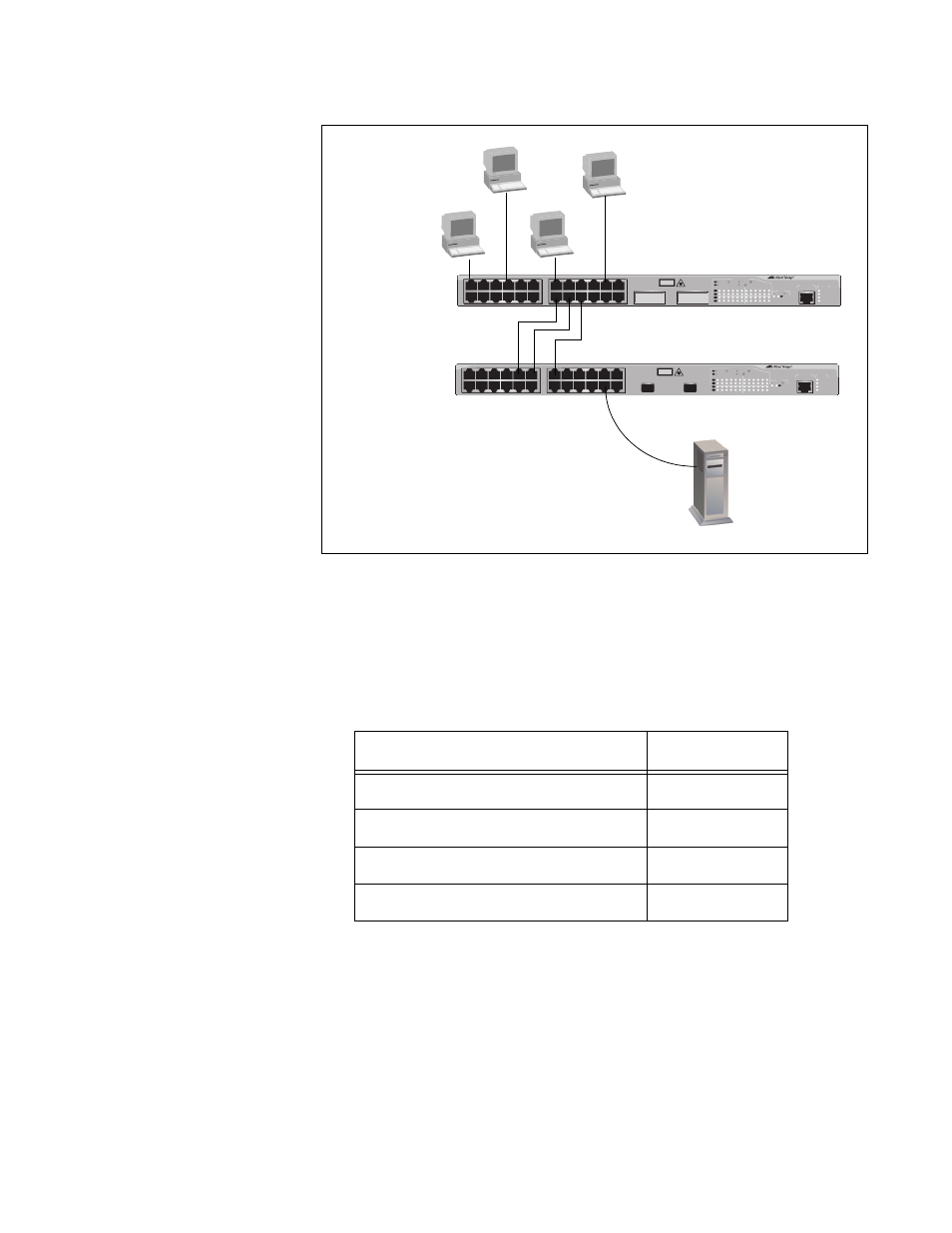
data link provided by an SFP transceiver in switch #2.
Figure 41. Load Distribution Method
Assume that you configured the port trunk on switch #1 with the source
MAC address load distribution method. The switch might distribute the
load as shown in Table 1.
For example, when workstation B sends a packet to the server, switch #1
uses port 15 of the trunk to transmit it to switch #2.
An assignment of a source address to a port trunk remains active as long
as the source node remains active. If the MAC address times out, the
assignment is dropped. If the source node becomes active again and
needs to transmit a packet over the trunk, a new assignment is made,
either to the same port or to a different port in the trunk.
FAULT
RPS
MASTER
POWER
CLASS 1
LASER PRODUCT
STATUS
TERMINAL
PORT
1
3
5
7
9
11
2
4
6
8
10
12
13
15
17
19
21
23R
14
16
18
20
22
24R
AT-9424T/SP
Gigabit Ethernet Switch
1
3
5
7
9
11
13
15
17
19
21
23R
2
4
6
8
10
12
14
16
18
20
22
24R
23
24
L/A
D/C
D/C
L/A
D/C
L/A
1000 LINK / ACT
HDX / COL
FDX
10/100 LINK / ACT
PORT ACTIVITY
L/A
1000 LINK / ACT
SFP
SFP
24
SFP
23
FAULT
RPS
MASTER
POWER
GBIC
23
GBIC
24
CLASS 1
LASER PRODUCT
STATUS
TERMINAL
PORT
1
3
5
7
9
11
2
4
6
8
10
12
13
15
17
19
21
23R
14
16
18
20
22
24R
AT-9424T/GB
Gigabit Ethernet Switch
1
3
5
7
9
11
13
15
17
19
21
23R
2
4
6
8
10
12
14
16
18
20
22
24R
23
24
L/A
D/C
D/C
L/A
D/C
L/A
1000 LINK / ACT
HDX / COL
FDX
10/100 LINK / ACT
PORT ACTIVITY
L/A
1000 LINK / ACT
GBIC
Workstation A
Workstation B
Workstation C
Workstation D
Switch #1
Switch #2
Table 1. Switch #1 - Source MAC Address Load Distribution
Source Address
Trunk Port
Workstation A - 00A0EE 2313A3
13
Workstation B - 00A134 1A9032
15
Workstation C -00A301 9083B2
13
Workstation B -001B21 87C6D6
17