Mixed stp and rstp networks, Spanning tree and vlans, Workstation (full-duplex mode) – Allied Telesis AT-S63 User Manual
Page 257: Class 1 laser product, L/a d/c d/c l/a d/c l/a
AT-S63 Management Software Menus Interface User’s Guide
Section II: Advanced Features
257
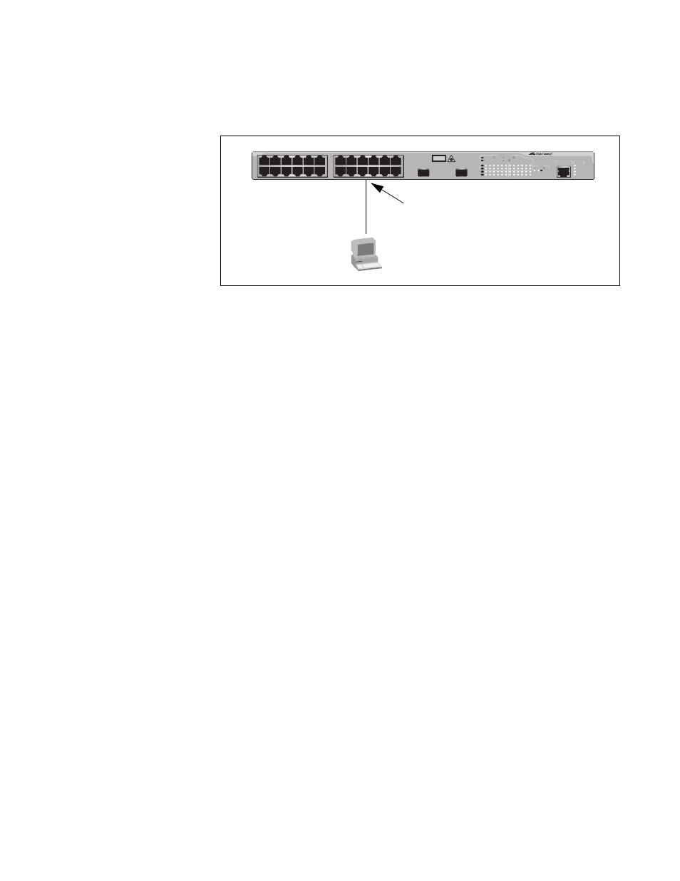
A port can be both a point-to-point and an edge port at the same time. It
operates in full-duplex and has no STP or RSTP devices connected to it.
Figure 76 illustrates a port functioning as both a point-to-point and edge
port.
Figure 76. Point-to-Point and Edge Port
Determining whether a bridge port is point-to-point, edge, or both, can
be a bit confusing. For that reason, do not change the default values for
this RSTP feature unless you have a good grasp of the concept. In most
cases, the default values work well.
Mixed STP and
RSTP Networks
RSTP IEEE 802.1w is fully compliant with STP IEEE 802.1d. Your network
can consist of bridges running both protocols. STP and RSTP in the same
network can operate together to create a single spanning tree domain.
If you decide to activate spanning tree on the switch, there is no reason
not to activate RSTP on an AT-9400 Series switch even when all other
switches are running STP. The switch can combine its RSTP with the STP
of the other switches. The switch monitors the traffic on each port for
BPDU packets. Ports that receive RSTP BPDU packets operates in RSTP
mode while ports receiving STP BPDU packets operate in STP mode.
Spanning Tree
and VLANs
The spanning tree implementation in the AT-S63 management software
is a single-instance spanning tree. The switch supports just one
spanning tree. You cannot define multiple spanning trees.
The single spanning tree encompasses all ports on the switch. If the
ports are divided into different VLANs, the spanning tree crosses the
VLAN boundaries. This point can pose a problem in networks containing
multiple VLANs that span different switches and are connected with
untagged ports. In this situation, STP blocks a data link because it
detects a data loop. This can cause fragmentation of your VLANs.
This issue is illustrated in Figure 77. Two VLANs, Sales and Production,
span two AT-9400 Series switches. Two links consisting of untagged
ports connect the separate parts of each VLAN. If STP or RSTP is activated
Point-to-Point and Edge Port
FAULT
RPS
MASTER
POWER
CLASS 1
LASER PRODUCT
STATUS
TERMINAL
PORT
1
3
5
7
9
11
2
4
6
8
10
12
13
15
17
19
21
23R
14
16
18
20
22
24R
AT-9424T/SP
Gigabit Ethernet Switch
1
3
5
7
9
11
13
15
17
19
21
23R
2
4
6
8
10
12
14
16
18
20
22
24R
23
24
L/A
D/C
D/C
L/A
D/C
L/A
1000 LINK / ACT
HDX / COL
FDX
10/100 LINK / ACT
PORT ACTIVITY
L/A
1000 LINK / ACT
SFP
SFP
24
SFP
23
Workstation
(Full-duplex Mode)