Rainbow Electronics DS3134 User Manual
Page 72
DS3134
72 of 203
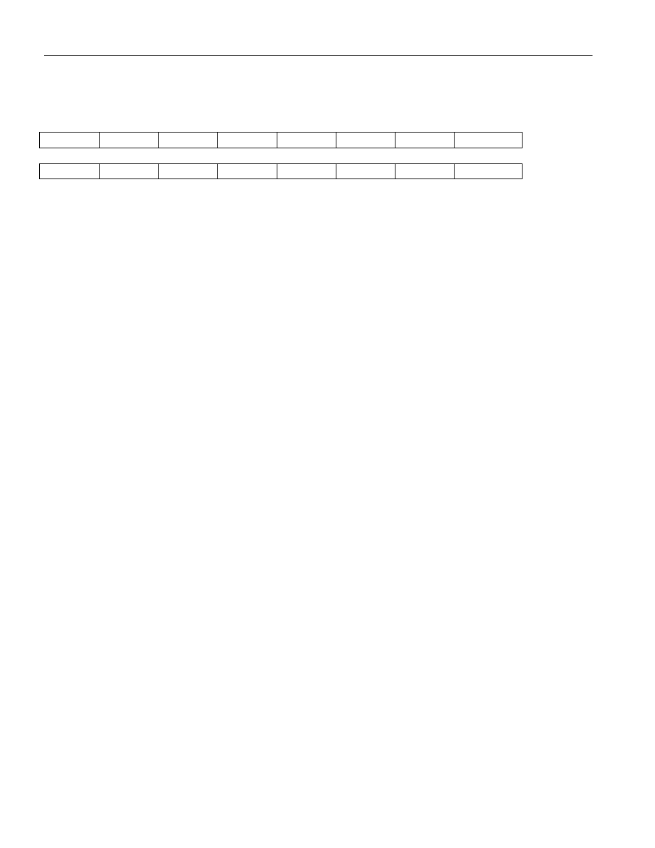
Register Name:
BERTC0
Register Description: BERT Control Register 0
Register Address:
0500h
7
6
5
4
3
2
1
0
n/a
TINV
RINV
PS2
PS1
PS0
LC
RESYNC
15
14
13
12
11
10
9
8
IESYNC
IEBED
IEOF
n/a
RPL3
RPL2
RPL1
RPL0
Note: Bits that are underlined are read only, all other bits are read-write; default value for all bits is 0.
Bit 0 / Force Resynchronization (RESYNC). A low to high transition will force the receive BERT
synchronizer to resynchronize to the incoming data stream. This bit should be toggled from low to high
whenever the host wishes to acquire synchronization on a new pattern. Must be cleared and set again for
a subsequent resynchronization. Note: Bit 2, 3 & 4 must be set, minimum of 64 system clock cycles,
before toggle the Resync bit (bit 0).
Bit 1 / Load Bit and Error Counters (LC). A low to high transition latches the current bit and error
counts into the host accessible registers BERTBC and BERTEC and clears the internal count. This bit
should be toggled from low to high whenever the host wishes to begin a new acquisition period. Must be
cleared and set again for a subsequent loads.
Bit 2 / Pattern Select Bit 0 (PS0).
Bit 3 / Pattern Select Bit 0 (PS1).
Bit 4 / Pattern Select Bit 1 (PS2).
000 = Pseudorandom Pattern 2E7 - 1
001 = Pseudorandom Pattern 2E11 - 1
010 = Pseudorandom Pattern 2E15 - 1
011 = Pseudorandom Pattern QRSS (2E20 - 1 with a one forced if the next 14 positions are zero)
100 = Repetitive Pattern
101 = Alternating Word Pattern
110 = illegal state
111 = illegal state
Bit 5 / Receive Invert Data Enable (RINV).
0 = do not invert the incoming data stream
1 = invert the incoming data stream
Bit 6 / Transmit Invert Data Enable (TINV).
0 = do not invert the outgoing data stream
1 = invert the outgoing data stream
Bit 8 / Repetitive Pattern Length Bit 0 (RPL0).
Bit 9 / Repetitive Pattern Length Bit 1 (RPL1).
Bit 10 / Repetitive Pattern Length Bit 2 (RPL2).