Receive done queue structure figure 8.1.4b – Rainbow Electronics DS3134 User Manual
Page 113
DS3134
113 of 203
Receive Done Queue Internal Address Storage Table 8.1.4A
Register Name
Acronym
Address
Receive Done Queue Base Address 0 (lower word)
RDQBA0
0730h
Receive Done Queue Base Address 1 (upper word)
RDQBA1
0734h
Receive Done Queue DMA Write Pointer
RDQWP
0740h
Receive Done Queue Host Read Pointer
RDQRP
073Ch
Receive Done Queue End Address
RDQEA
0738h
Receive Done Queue FIFO Flush Timer
RDQFFT
0744h
Note:
1) Receive Done Queue End Address is not an absolute address. The absolute end address is “Base +
RDQEA * 4 ”.
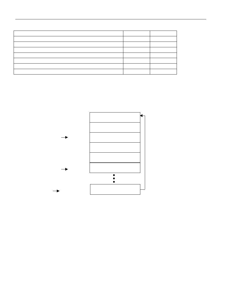
Receive Done Queue Structure Figure 8.1.4B
Once the Receive DMA is activated (via the RDE control bit in the Master Configuration register; see
Section 4 for more details), it can begin writing data to the Done Queue. It knows where to write data
into the Done Queue by reading the Write Pointer and adding it to the Base Address to obtain the actual
32-bit address. Once the DMA has written to the Done Queue, it increments the Write Pointer by one
dword. A check must be made to make sure the incremented address does not exceed the Receive Done
Queue End Address. If the incremented address does exceed this address, then the incremented write
pointer will be set equal to 0000h (i.e. the Base Address).
dmardq
Base + 00h
Base + 04h
Base + 08h
Base + 0Ch
Base + 10h
Base + 14h
Base + End Address
Done Queue DMA Write Pointer
Done Queue Host Read Pointer
Maximum of 65536
Done Queue Descriptors
DMA Readied
Done Queue Descriptor
DMA Readied
Done Queue Descriptor
DMA Readied
Done Queue Descriptor
DMA Readied
Done Queue Descriptor
Host Processed
Done Queue Descriptor
Host Processed
Done Queue Descriptor
Host Processed
Done Queue Descriptor