Rainbow Electronics DS3134 User Manual
Page 121
DS3134
121 of 203
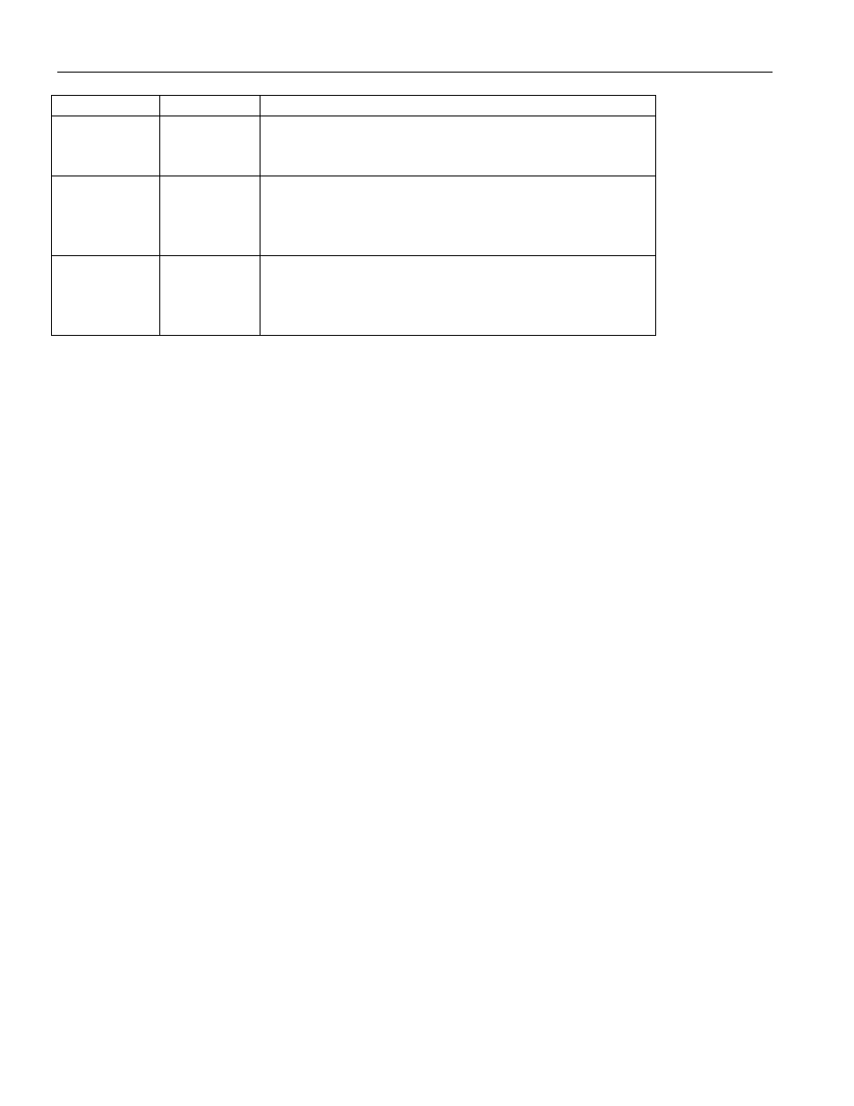
Transmit DMA Main Operational Areas Table 8.2.1A
Name
Section
Description
Packet
Descriptors
8.2.2
A dedicated area of memory that describes the location
and attributes of the packet data.
Pending
Queue
Descriptors
8.2.3
A dedicated area of memory that the Host will write to
inform the DMA that packet data is queued and ready
for transmission
Done Queue
Descriptors
8.2.4
A dedicated area of memory that the DMA will write to
inform the Host that the packet data has been
transmitted
Host Linking of Data Buffers
As mentioned earlier, the data buffers are limited to a length of 8191 bytes. If an outgoing packet requires
more memory space than the available data buffer contains, then the Host can link multiple data buffers
together to handle a packet length of any size. The Host does this via the End Of Frame (EOF) bit in the
Packet Descriptor. Each data buffer has a one-to-one association with a Packet Descriptor. If the Host
wishes to link multiple data buffers together, then the EOF bit will be set to zero in all but the last data
buffer. Figure 8.2.1A contains an example for HDLC channel number 5 where the Host has linked three
data buffers together. The transmit DMA knows where to find the next data buffer when the EOF bit is
set to zero via the Next Descriptor Pointer field.
Host Linking of Packets (Packet Chaining)
The Host also has the option to link multiple packets together in a chain. Via the Chain Valid (CV) bit in
the Packet Descriptor, the Host can inform the transmit DMA that the Next Descriptor Pointer field
contains the descriptor of another HDLC packet that is ready for transmission. The transmit DMA
ignores the CV bit until it sees EOF = 1 which indicates the end of a packet. If CV = 1 when EOF = 1,
then this indicates to the transmit DMA that it should use the Next Descriptor Pointer field to find the
next packet in the chain. Figure 8.2.1C provides an example of packet chaining. Each column in Figure
8.2.1C represents a separate packet chain. In column 1, three data buffers have been linked together by
the Host for Packet #1 and then the Host has created a packet chain by setting CV = 1 in the last
descriptor of Packet #1.