5 bert, Bert mux diagram figure 5.5a – Rainbow Electronics DS3134 User Manual
Page 70
DS3134
70 of 203
5.5 BERT
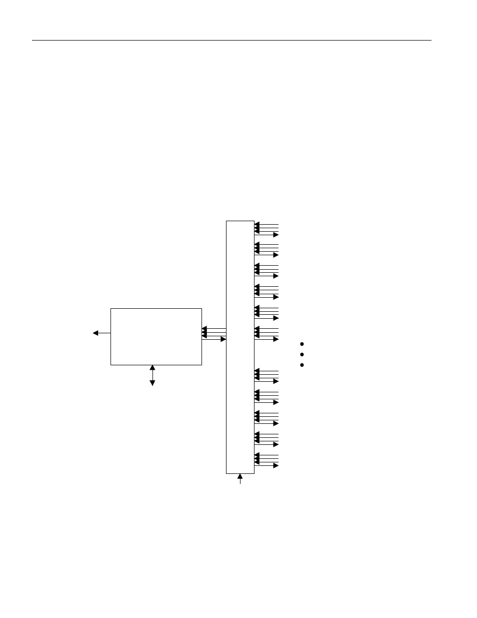
The BERT Block is capable of generating and detecting the following patterns:
- The pseudorandom patterns 2E7, 2E11, 2E15, and QRSS
- A repetitive pattern from 1 to 32 bits in length
- Alternating (16-bit) words which flip every 1 to 256 words
The BERT receiver has a 32-bit Bit Counter and a 24-bit Error Counter. It can generate interrupts on
detecting a bit error, a change in synchronization, or if an overflow occurs in the Bit and Error Counters.
See Section 4 for details on status bits and interrupts from the BERT Block. To activate the BERT Block,
the Host must configure the BERT mux (see Figure 5.5A) and in channelized applications, the Host must
also configure the Layer One State Machine to send/obtain data to/from the BERT Block via the Layer
One Configuration Registers (see Section 5.3).
BERT Mux Diagram Figure 5.5A
Port 0 (slow)
Port 1 (slow)
Port 2 (slow)
Port 3 (slow)
Port 4 (slow)
Port 5 (slow)
bertbd
BERT
Mux
BERT
Block
SBERT Status Bit
in SM
Internal Control &
Configuration Bus
Port 13 (slow)
Port 14 (slow)
Port 15 (slow)
Port 0 (fast)
Port 1 (fast)
BERT Select (5)
In the Master Configuration
Register