Rainbow Electronics DS3134 User Manual
Page 155
DS3134
155 of 203
Bits 24 to 31 / Class Code Base Class. These read only bits identify the base class value for the device
and are fixed at 02h, which indicate "Network Controllers". See Appendix D of PCI Local Bus
Specification Revision 2.1 for details.
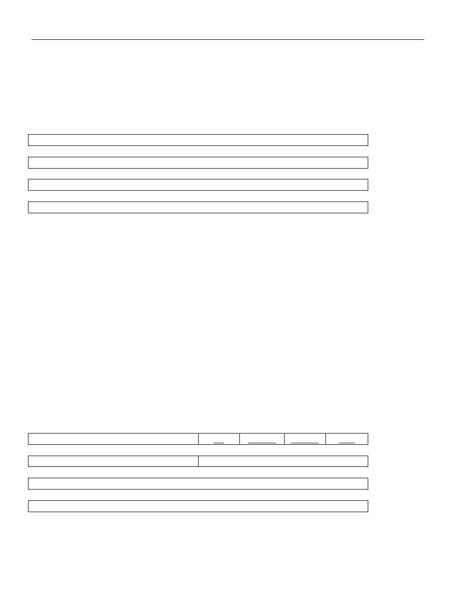
Register Name:
PLTH0
Register Description: PCI Latency Timer / Header Type Register 0
Register Address:
0x00Ch
lsb
Cache Line Size
Latency Timer
Header Type (Read Only / set to 80h)
msb
BIST (Read Only / set to 00h)
Bits 0 to 7 / Cache Line Size. These read/write bits indicates the cache line size in terms of dwords. If
the burst size of a data read transaction exceeds this value, then the PCI Block will use the memory read
multiple command. Valid settings are 04h (4 dwords), 08h, 10h, 20h, and 40h (64 dwords). Other
settings are interpreted as 00h. These bits are forced to zero when a hardware reset is initiated via the
PRST* pin.
Bits 8 to 15 / Latency Timer. These read/write bits indicate the value of the Latency Timer (in terms of
the number of PCI clocks) for use when the device is a bus master. These bits are forced to zero when a
hardware reset is initiated via the PRST* pin.
Bits 16 to 23 / Header Type. These read only bits are forced to 80h, which indicate a multifunction
device.
Bits 24 to 31 / Built-In Self-Test (BIST). These read only bits are forced to zero.
Register Name:
PDCM
Register Description: PCI Device Configuration Memory Base Address Register
Register Address:
0x010h
lsb
Base Address (Read Only / set to 0h)
PF
TYPE1
TYPE0
MSI
Base Address
Base Address (Read Only / set to 0h)
Base Address
msb
Base Address