Rainbow Electronics DS3134 User Manual
Page 45
DS3134
45 of 203
Bit 4 / Status Bit for PCI System Error (PPERR). This status bit is a software version of the PCI Bus
hardware pin PPERR. It will be set to a one if the PCI Bus detects parity errors on the PAD and PCBE*
buses as experienced or reported by a target. The PPERR bit will be cleared when read and will not be set
again until another parity error has been detected. If enabled via the PPERR bit in the Interrupt Mask for
SM (ISM), the setting of this bit will cause a hardware interrupt at the PCI Bus via the PINTA* signal pin
and also at the LINT* if the Local Bus is in the Configuration Mode. This status bit is also reported in the
Control/Status register in the PCI Configuration registers, see Section 9 for more details.
Bit 14 / Status Bit for Local Bus Error (LBE). This status bit applies to the Local Bus when it is
operate d in the PCI Bridge Mode. It will be set to a one when the Local Bus LRDY* signal is not
detected within nine LCLK periods. This indicates to the Host that an aborted Local Bus access has
occurred. If enabled via the LBE bit in the Interrupt Mask for SM (ISM), the setting of this bit will cause a
hardware interrupt at the PCI Bus via the PINTA* signal pin and also at the LINT* if the Local Bus is in
the Configuration Mode. The LBE bit is meaningless when the Local Bus is operated in the configuration
mode and should be ignored.
Bit 15 / Status Bit for Local Bus Interrupt (LBINT). This status bit will be set to a one if the Local
Bus LINT* signal has been detected as asserted. This status bit is only valid when the Local Bus is
operated in the PCI Bridge Mode. The LBINT bit will be cleared when read and will not be set again
until once again the LINT* signal pin has been detected as asserted. If enabled via the LBINT bit in the
Interrupt Mask for SM (ISM), the setting of this bit will cause a hardware interrupt at the PCI Bus via the
PINTA* signal pin. The LBINT bit is meaningless when the Local Bus is operated in the configuration
mode and should be ignored.
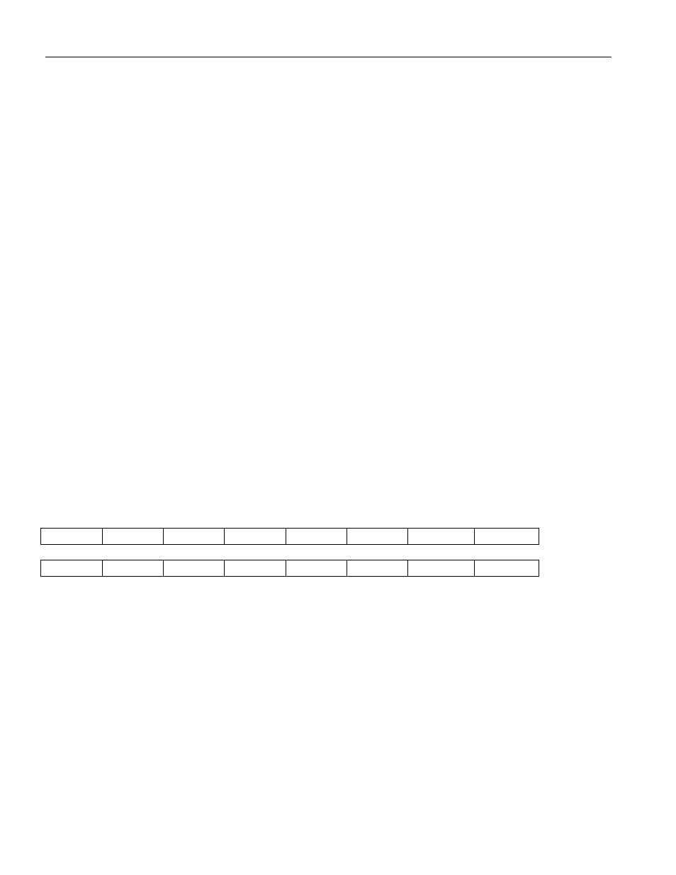
Register Name:
ISM
Register Description: Interrupt Mask Register for SM
Register Address:
0024h
7
6
5
4
3
2
1
0
n/a
n/a
n/a
PPERR
PSERR
SBERT
STCOFA
SRCOFA
15
14
13
12
11
10
9
8
LBINT
LBE
n/a
n/a
n/a
n/a
n/a
n/a
Note: Bits that are underlined are read only, all other bits are read-write; default value for all bits is 0.
Bit 0 / Status Bit for Receive Change Of Frame Alignment (SRCOFA).
0 = interrupt masked
1 = interrupt unmasked
Bit 1 / Status Bit for Transmit Change Of Frame Alignment (STCOFA).
0 = interrupt masked
1 = interrupt unmasked
Bit 2 / Status Bit for Change of State in BERT (SBERT).
0 = interrupt masked
1 = interrupt unmasked