Rainbow Electronics DS3134 User Manual
Page 145
DS3134
145 of 203
SECTION 9: PCI BUS
9.1 PCI GENERAL DESCRIPTION OF OPERATION
The PCI Block interfaces the DMA Block to an external high-speed bus. The PCI Block complies with
Revision 2.1 (June 1, 1995) of the PCI Local Bus Specification. HDLC packet data will always pass to
and from Chateau via the PCI bus. The user has the option to configure and monitor the internal device
registers either via the PCI bus (Local Bus Bridge mode) or via the Local Bus (Local Bus Configuration
mode). When the Local Bus Bridge mode is used, the Host on the PCI bus can also bridge to the Local
Bus and will set/monitor the PCI Configuration registers. When the Local Bus Configuration mode is
used, the CPU on the Local Bus will set/monitor the PCI Configuration registers.
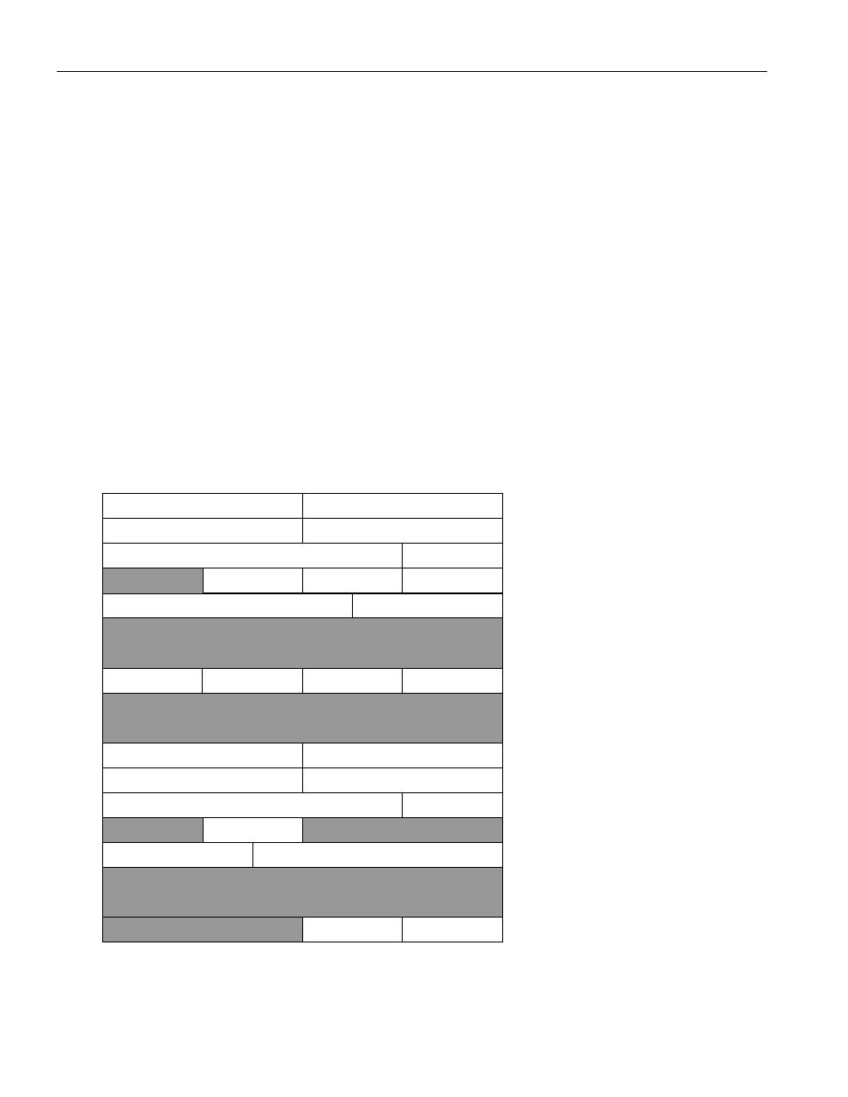
The PCI Configuration registers (see Figure 9.1A) are described in detail in Section 9.2. The following is
a set of notes that apply to the PCI Configuration registers:
1. All unused locations (the shaded areas of Figure 9.1A) will return zeros when read
2. Read only locations can be written with either a one or zero with no affect
3. All bits are read/write unless otherwise noted.
PCI Configuration Memory Map Figure 9.1A
0x000
0x004
0x008
0x00C
0x010
0x03C
0x100
0x104
0x108
0x10C
0x110
Device ID
Vendor ID
Status
Command
Class Code
Revision ID
Header Type
Latency Timer
Base Address for Device Configuration
0x000
Max. Latency
Min. Grant
Interrupt Pin
Interrupt Line
Header Type
Device ID
Vendor ID
Status
Command
Class Code
Revision ID
0x00000
Base Address for Local Bus
Cache Line Size
Interrupt Pin
Interrupt Line
0x13C
pci_reg