Application drawing key figure 14a, Single t1/e1 connection figure 14b – Rainbow Electronics DS3134 User Manual
Page 199
DS3134
199 of 203
SECTION 14: APPLICATIONS
Section 14 describes some possible applications for the DS3134. The number of potential configurations
is numerous and only a few are shown. Users are encouraged to contact the factory for support of their
particular application. Contact information is shown in Table 14A.
Telecom Applications Support Contact Information Table 14A
web
www.dalsemi.com
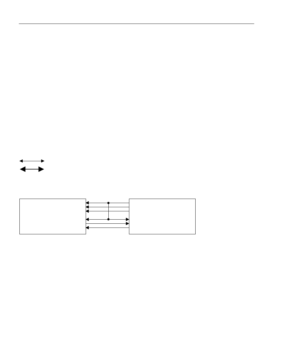
The T1 and E1 channelized application examples shown in Section 14 will be one of two types. The first
type is where a single T1 or E1 data stream is routed to and from the DS3134. This first type is
represented as a thin arrow in the application examples and the electrical connections are shown in
Figure 14B. The second type is where four T1 or E1 data streams have been Time Division Multiplexed
(TDM) into a single 8.192 MHz data stream, which is routed to and from the DS3134. This second type
is represented as a thick arrow and the electrical connections are shown in Figure 14C.
Application Drawing Key Figure 14A
Single T1 or E1 Line at 1.544MHz or 2.048MHz
Quad (4) T1 or E1 Lines Byte Interleaved at 8.192M
1x
4x
Single T1/E1 Connection Figure 14B
RCLK
RSER
RSYNC
TCLK
TSER
TSYNC
RC
RD
RS
TC
TS
TD
DS3134
CHATEAU
Dallas Framer or
Transceiver
(elastic stores
disabled)
Note:
A looped timed application is shown. The transmit clock may be decoupled from the receive in applications
that are a timing master.
Single T1/E1 Line Connection
app_ovr