Rainbow Electronics DS3134 User Manual
Page 46
DS3134
46 of 203
Bit 3 / Status Bit for PCI System Error (PSERR).
0 = interrupt masked
1 = interrupt unmasked
Bit 4 / Status Bit for PCI System Error (PPERR).
0 = interrupt masked
1 = interrupt unmasked
Bit 14 / Status Bit for Local Bus Error (LBE).
0 = interrupt masked
1 = interrupt unmasked
Bit 15 / Status Bit for Local Bus Interrupt (LBINT).
0 = interrupt masked
1 = interrupt unmasked
Register Name:
SV54
Register Description: Status Register for the Receive V.54 Detector
Register Address:
0030h
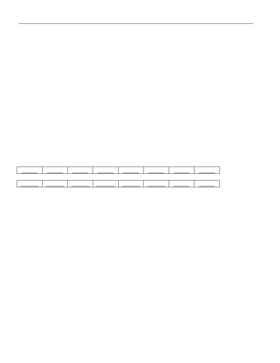
7
6
5
4
3
2
1
0
SLBP7
SLBP6
SLBP5
SLBP4
SLBP3
SLBP2
SLBP1
SLBP0
15
14
13
12
11
10
9
8
SLBP15
SLBP14
SLBP13
SLBP12
SLBP11
SLBP10
SLBP9
SLBP8
Note: Bits that are underlined are read only, all other bits are read-write; default value for all bits is 0.
Bits 0 to 15 / Status Bit for Change of State in Receive V.54 Loopback Detector (SLBP0 to
SLBP15). These status bits will be set to a one when the V.54 loopback detector within the port has
either timed out in its search for the loop up pattern or it has detected and validated the loop up or down
pattern. There is one status bit per port. The Host must read the VTO and VLB status bits in RP[n]CR
register of the corresponding port to determine the exact status of the V.54 detector. If the V.54 detector
has timed out in it's search for the loop up code (VTO = 1), then SLBP will be continuously set until the
Host resets the V.54 detector by toggling the VRST bit in RP[n]CR. If enabled via the SLBP[n] bit in the
Interrupt Mask for SV54 (ISV54), the setting of these bits will cause a hardware interrupt at the PCI Bus
via the PINTA* signal pin and also at the LINT* if the Local Bus is in the Configuration Mode. See
Section 5 for specific details on the operation of the V.54 loopback detector.