EVS XT3 Version 11.00 Configuration Manual User Manual
Page 112
IN6/OUT1
IN5/OUT2
IN4/OUT3
IN3/OUT4
IN2/OUT5
IN1/OUT6
#REC
#PLAY
Prim.
Link
Sec.
Link
Prim.
Link
Sec.
Link
Prim.
Link
Sec.
Link
Prim.
Link
Sec.
Link
Prim.
Link
Sec.
Link
Prim.
Link
Sec.
Link
1
3
PLAY
1A
PLAY
1B
PLAY
2A
PLAY
2B
PLAY
3A
PLAY
3B
REC
1A
REC
1B
2
3
PLAY
1A
PLAY
1B
PLAY
2A
PLAY
2B
PLAY
3A
PLAY
3B
REC
2A
REC
2B
REC
1A
REC
1B
3
3
PLAY
1A
PLAY
1B
PLAY
2A
PLAY
2B
PLAY
3A
PLAY
3B
REC
3A
REC
3B
REC
2A
REC
2B
REC
1A
REC
1B
0
4
PLAY
1A
PLAY
1B
PLAY
2A
PLAY
2B
PLAY
3A
PLAY
3B
PLAY
4A
PLAY
4B
1
4
PLAY
1A
PLAY
1B
PLAY
2A
PLAY
2B
PLAY
3A
PLAY
3B
PLAY
4A
PLAY
4B
REC
1A
REC
1B
2
4
PLAY
1A
PLAY
1B
PLAY
2A
PLAY
2B
PLAY
3A
PLAY
3B
PLAY
4A
PLAY
4B
REC
2A
REC
2B
REC
1A
REC
1B
1
5
PLAY
1A
PLAY
1B
PLAY
2A
PLAY
2B
PLAY
3A
PLAY
3B
PLAY
4A
PLAY
4B
PLAY
5A
PLAY
5B
REC
1A
REC
1B
0
6
PLAY
1A
PLAY
1B
PLAY
2A
PLAY
2B
PLAY
3A
PLAY
3B
PLAY
4A
PLAY
4B
PLAY
5A
PLAY
5B
PLAY
6A
PLAY
6B
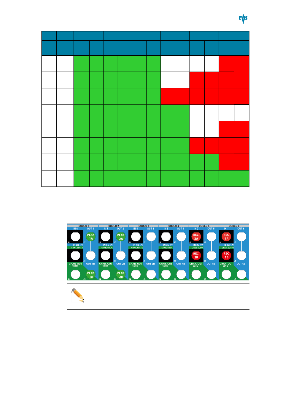
Example : 3D/1080p Dual Link 2REC + 2 PLAY
The BNC connectors to be used as record and play channels in a 3D or 1080p Dual Link
configuration 2REC + 2PLAY need to be cabled as shown below:
Note
In an equivalent configuration with a 3G interface, only the J8 connectors are
cabled. However the primary and secondary links on the codec module of the
V3X board are both used.
XT3 Server - Version 11.00 - Configuration Manual
3. Multicam Configuration
106
- XFReader Version 2.6 - October 2013 User Manual (44 pages)
- Xfile Version 2.14 - January 2011 User Manual (190 pages)
- MulticamLSM Version 9.00 - March 2008 User's Manual (201 pages)
- XstoreSE (4 pages)
- XEDIO Importer Version 3.1 - January 2011 User Manual (34 pages)
- Xfile Version 1.01 - December 2006 User Manual (42 pages)
- XTract Version 1.01 - January 2011 User Manual (15 pages)
- MulticamLSM Version 8.03 - Dec 2006 User's Manual (156 pages)
- IPDirector Version 6.2 - June 2013 CHANNEL EXPLORER User Manual (48 pages)
- XS Version 11.02 - July 2013 Configuration Manual (204 pages)
- GX Version 1.00 - February 2011 User’s Manual (66 pages)
- LSM Connect (32 pages)
- MulticamLSM Version 10.01 - July 2009 Operating Manual (185 pages)
- XStoreSAN (4 pages)
- XTract Installation Note (1 page)
- MulticamLSM Version 10.03 - July 2010 Configuration Manual (97 pages)
- XTAccess Version 1.18 - July 2012 User Manual (109 pages)
- XEDIO Manager Version 3.1 - January 2011 User Manual (134 pages)
- EpsioAir (2 pages)
- XSense Version 10.04 - January 2011 Operating Manual (164 pages)
- MultiReview (2 pages)
- XEDIO Media Cleaner Version 3.1 - January 2011 User Manual (16 pages)
- XEDIO Media Cleaner Version 3.1 - January 2011 User Manual (18 pages)
- XEDIO Media Cleaner Version 4.1 - December 2011 User Manual (17 pages)
- XEDIO Playout Organizer Version 4.35 - August 2013 User Manual (36 pages)
- IPDirector Version 6.0 - November 2012 Part 2 User's Manual (92 pages)
- IPWeb Version 1.0 - June 2013 User Manual (76 pages)
- XEDIO Ingest Organizer Version 3.1 - January 2011 User Manual (22 pages)
- XTnano Version 11.02 - July 2013 Operation Manual (102 pages)
- Xfile Version 2.13 - July 2010 User Manual (192 pages)
- IP2Archive Version 1.2 - October 2012 User Manual (30 pages)
- XEDIO Importer Version 4.35 - August 2013 User Manual (38 pages)
- XTract Version 1.00 - May 2010 User Manual (16 pages)
- XEDIO Browse Version 3.1 - January 2011 User Manual (38 pages)
- EPSIO Version 1.63 - May 2011 User's Manual (73 pages)
- IPDirector Version 6.0 - November 2012 Part 10 User's Manual (30 pages)
- IPDirector Version 6.2 - June 2013 IPLOGGER User Manual (74 pages)
- IPDirector Version 5.8 - July 2010 Part 7 User's Manual (229 pages)
- XFLY Streamer Version 1.02 - April 2013 User Manual (25 pages)
- OpenCube MXFTK Version 2.6 - October 2013 User Manual (42 pages)
- IPDirector Version 4.3 - October 2007 Part 3 User's Manual (204 pages)
- IP2Archive Deep Archive Sync Version 1.1 - October 2012 User Manual (66 pages)
- XEDIO Playout Organizer Version 3.1 - January 2011 User Manual (29 pages)
- MulticamLSM Version 10.04 - January 2011 Configuration Manual (98 pages)
- XTAccess Version 1.19 - November 2012 User Manual (112 pages)