Samsung S3C2440A User Manual
Page 395
S3C2440A RISC MICROPROCESSOR
LCD CONTROLLER
15-27
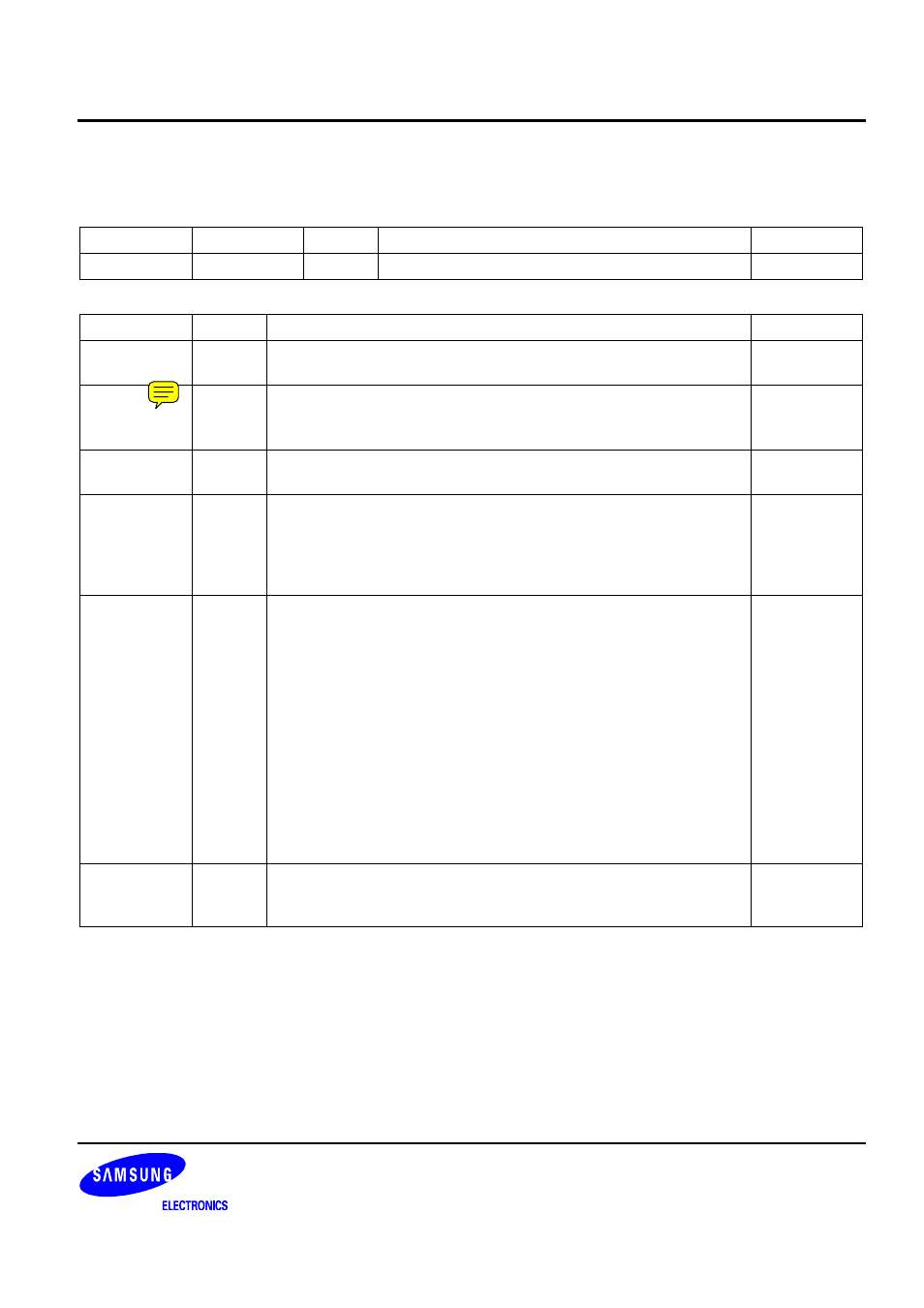
LCD CONTROLLER SPECIAL REGISTERS
LCD Control 1 Register
Register Address R/W
Description
Reset
Value
LCDCON1
0X4D000000
R/W
LCD control 1 register
0x00000000
LCDCON1 Bit
Description
Initial
State
LINECNT
(read only)
[27:18]
Provide the status of the line counter.
Down count from LINEVAL to 0
0000000000
CLKVAL
[17:8]
Determine the rates of VCLK and CLKVAL[9:0].
STN: VCLK = HCLK / (CLKVAL x 2) ( CLKVAL
≥
2 )
TFT: VCLK = HCLK / [(CLKVAL+1) x 2] ( CLKVAL
≥
0 )
0000000000
MMODE
[7]
Determine the toggle rate of the VM.
0 = Each Frame
1 = The rate defined by the MVAL
0
PNRMODE
[6:5]
Select the display mode.
00 = 4-bit dual scan display mode (STN)
01 = 4-bit single scan display mode (STN)
10 = 8-bit single scan display mode (STN)
11 = TFT LCD panel
00
BPPMODE
[4:1]
Select the BPP (Bits Per Pixel) mode.
0000 = 1 bpp for STN, Monochrome mode
0001 = 2 bpp for STN, 4-level gray mode
0010 = 4 bpp for STN, 16-level gray mode
0011 = 8 bpp for STN, color mode (256 color)
0100 = packed 12 bpp for STN, color mode (4096 color)
0101 = unpacked 12 bpp for STN, color mode (4096 color)
0110 = 16 bpp for STN, color mode (4096 color)
1000 = 1 bpp for TFT
1001 = 2 bpp for TFT
1010 = 4 bpp for TFT
1011 = 8 bpp for TFT
1100 = 16 bpp for TFT
1101 = 24 bpp for TFT
0000
ENVID
[0]
LCD video output and the logic enable/disable.
0 = Disable the video output and the LCD control signal.
1 = Enable the video output and the LCD control signal.
0