RIGOL DG1000Z Series User Manual
Page 45
RIGOL
DG1000Z Programming Guide
2-33
*RCL
Syntax
*RCL
{USER1|USER2|USER3|USER4|USER5|USER6|USER7|USER8|USER9|USER10|
ARB1|ARB2|ARB3|ARB4|ARB5|ARB6|ARB7|ARB8|ARB9|ARB10}
Description
Recall the state file (USER) or arbitrary waveform file (ARB) stored in the specified
location in the internal non-volatile memory.
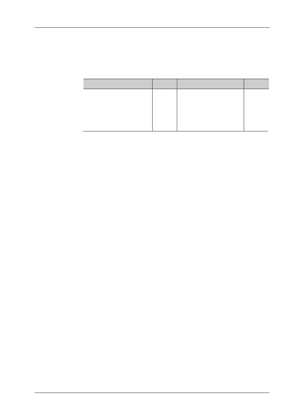
Parameter
Name
Type
Range
Default
{USER1|USER2|USER3|
USER4|USER5|USER6|
USER7|USER8|USER9|
USER10|ARB1|ARB2|ARB3|
ARB4|ARB5|ARB6|ARB7|
ARB8|ARB9|ARB10}
Discrete
USER1|USER2|USER3|
USER4|USER5|USER6|
USER7|USER8|USER9|
USER10|ARB1|ARB2|ARB3|
ARB4|ARB5|ARB6|ARB7|
ARB8|ARB9|ARB10
None
Explanation
The instrument provides 10 storage locations (numbered 1 to 10) in the
internal memory for storing the state files and arbitrary waveform files
respectively. Sending this command can recall the state file or arbitrary
waveform file stored in the specified storage location in the internal
non-volatile memory. Select number 1 to 10 to recall the state file or arbitrary
waveform file stored in the corresponding storage location respectively.
This command is only valid when an effective state file or arbitrary waveform
file is stored in the specified storage location in the internal non-volatile
memory.
The state file stored includes the waveforms, frequencies, amplitudes, offsets,
duty cycles, symmetries, phases, the modulation, sweep, burst parameters,
the frequency counter parameters of the two channels as well as the utility
parameters and system parameters under the Utility menu.
The arbitrary waveform file stores the voltage corresponding to each
waveform point in binary data form. In the sample rate editing mode, there are
only Sa points if the number of points is set to Sa and the voltage of each
point is the voltage set by users. In the period editing mode, if the number of
points is set to Sa, the voltages of the first Sa points is the voltages set by
users and the voltages of the (Sa+1)
th
point to 8192
nd
point are low level. The
voltage of each point occupies 2 bytes (namely 16 bits); wherein, the 14
low-order bits denote the voltage and the 2 high-order bits are not used.
Therefore, the format of the binary data is 0x0000 to 0x3FFF; wherein, 0x0000
corresponds to the low level of the arbitrary waveform and 0x3FFF
corresponds to the high level of the arbitrary waveform.