Yaskawa J50M Instructions User Manual
Page 99
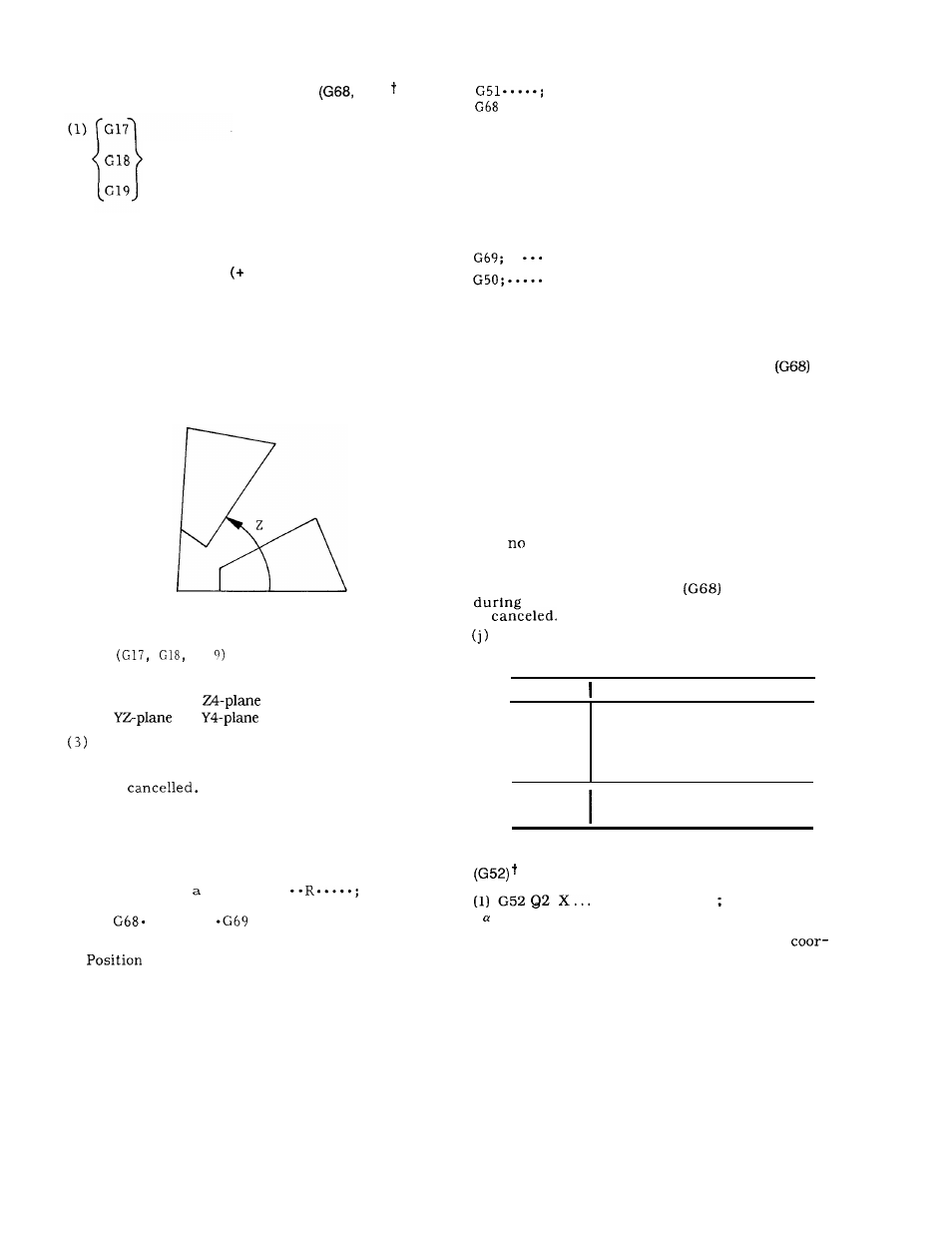
2.9.33 ROTATION OF COORDINATES
G69)
G68
a . . . .. b . . . .. R......
Where,
a, b:
Values of coordinates of the center of
rotation
R:
Angle of rotation
for counterclockwise
direction, and absolute value is to be used for
command)
By commanding with the above, the commands
thereafter are rotated by the value of the angle
assigned by R around the center commanded by
point a, b.
The angle of rotation must be com-
manded in 0.001 degree units.
(a, b)
(2) Plane of rotation is determined by the
plane
G] that has been selected.
G
17 XY-plane or X4-plane
G 18 ZX-plane or
1
(But the 4th axis is
G 1 9
or
limited to linear axis.)
G69;
When this is commanded, the coordinate rotation
mode is
(4) Note:
(a)
If a and b are omitted, the position where
the command of G68 was made becomes the center
of rotation.
Omission of R is not permitted.
(b) Blocks of G68 . . . . . . . . .
and G69;
must be commanded by a single block.
Be sure
to use
. . . . . . .
in pairs for the rotation
of coordinates.
(c)
display shows the position where the
rotation of coordinates was commanded.
(d) When using together with scaling functions,
the rotation of the coordinate system is made after
turning-on scaling, and thus the command should
be made in the following order:
. . . . . .
.
.
.
.
. .
( e ) G 6 8 ,
(Scaling on)
( Coordinate rotation on)
(Coordinate rotation off )
(Scaling off)
G69 are modal G codes of group 18.
(f)
G69
is automatically selected during power
turn-on or reset operation.
(g) Commanding the rotation of coordinates
is not
possible during tool radius compensation C. It causes an
alarm.
(h)
The following G codes cannot be commanded
during the rotation of coordinates:
They activate
alarms.
G29, G31, G36, G37, G38, G53 and G92
(i) ‘The rotation of coordinates turns on during
the approach of ordinary machining and turns off
upon completion of machining.
It should be noted
that
proper machining shape is obtained if the
rotation of coordinates is turned on during
machining.
If the rotation of coordinates
is commanded
the canned cycles, the canned cycle mode
is
Alarm codes related to the rotation of coor-
dinates are as follows:
Alarm No.
Contents
150
G
code not to be used in G68
mode has been commanded.
G68 is commanded again when
a G68 command is executed.
151
Format of G68, G69 command
blocks is not correct.
2.9.34 SETTING OF LOCAL COORDINATE SYSTEM
Z . . . Z . . . a . . .
( indicates the 4th axis.)
When the above command is issued, a
dinate system shifted by the corresponding
commanded value from the work coordinate system
is set.
This coordinate system is called the local coor-
dinate system,
and thereafter the tool moves on
this assigned local coordinate system.
91