Yaskawa J50M Instructions User Manual
Page 109

b. When system variable #1132 is specified, the
output signals (UOO through
that consist
of 16 points ( 16 bits) are collectively output.
At this time, the decimal positive value substituted
in #1 132 is output in the form of binary 16–bit
value.
#1132 =
#[1100 + i] * 2i
i = O
c. With system variables # 1100 through
1132, the
value sent last is retained. When one of them is written to
the right-hand of an operational expression, its value is
read.
d . C o n s i d e r a t i o n s
When any values other than
or
are sub-
stituted into one of #1 100 through #1 115, the
values are handled as follows:
“Blank” is assumed to be “O. ”
Values other than “blank” and O are assumed to
be
Sample Program
= #lo ; (#lo =
1 . 5 )
The output signal of bit 2
7
is output
in the contact (closed) state.
#1132 = (#1132 AND 240) OR (#8 AND
The value of the last sending data is stored in system
#1100 to #1132. Therefore, when these system
are
at the right side of the equation, the
values are read in.
The output signal Of bits
through 27 (uo4
through
are output without change and
the contents of local variable #8 are output
to the output signals of bits
through 23
(UOO through U03) .
(Decimal 240) = 11110000
(Decimal 15) = 00001111
C. Tool Offset Amount and Work Coordinate System
Shift Amount (#2001 through #2299, #2500 through
#2906)
a. When one of system variables #2001 through
#2299 is specified to the right-hand of an opera-
tional expression, the tool offset amount can be
r e a d .
b. When one of system variables #2500 through
#2906 is specified to the right-hand of an opera-
tional expression, the work coordinate system
shift amount ( and the external work coordinate
correction amount) can be read.
c.
The relationships between the tool offset
and the system variables are as shown
below :
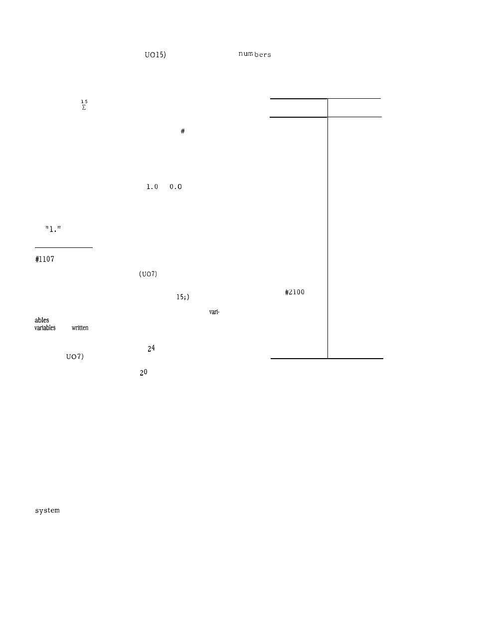
Table 2.35 System Variables
and Tool offset No.
System
Variable
#2001
#2002
#2098
#2099
#2299
Tool
Offset No.
01
02
98
99
100
299
101
