Yaskawa J50M Instructions User Manual
Page 172
5.
UNITS ON THE
Fig.
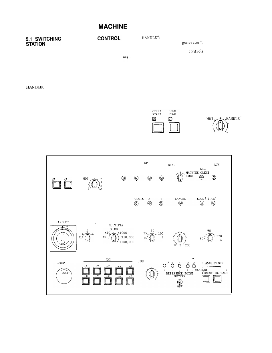
5.1
shows the layout of switching unit on
the control station For details , refer to the
chine tool builder’s manual.
5.1.1
MODE SELECT SWITCH
This switch gives the operator a choice among the fol-
lowing eight modes of operation (RAPID, JOG, STEP,
TAPE, MDI, MEM, EDT).
RAPID : Allows the tool to traverse rapidly or return
to reference point by manual operation.
JOG:
Allows the tool to feed continuously by
manual operation . Feedrate is set by JOG
FEEDRATE switch.
STEP : Allows the tool to feed manually by step
each time JOG pushbutton is depressed.
CONTROL STATION
Allows the tool to feed by operating
the manual pulse
TAPE: Automatically
the system from
NC tape.
MDI :
A
I 1
OWS
the operator to write reference value
and execute the contents.
MEM: Automatically controls the system with the
stored part program.
EDT : Stores the part program into memory and
edit the part program.
MODE SELECT
TAPE
MEM
STEP
JOG
EDT
RAPID
Fig. 5.2
CYCLE FEED
START HOLD
MoDE SELECT
TAPE
HANDLE”!
MEM
STEP
JOG
EDT “
PID
oP-
TIONAL
Z-AXIS
SINGLE TIONAL BLOCK DRY
PLAY OFF
FUNCTION
LOCK
LOCK
BLOCK STOP
SKIP
RUN
OFF
OFF
OFF
OFF
OFF
OFF
MIRROR IMAGE
MANUAL
AXIS
OVERRIDE
START EDIT
ABSOLUTE X
CANCEL
L
OC
K
OFF
OFF
OFF
OFF
OFF
NANUAL
HANDLE
PULSE
RAPID TRAVERSE
AXIS
FEEDRATE
SPINDLE-SPEED
RATE OVERRIDE
OVERRIDE
OVERRIDE?
EMERGENCY
REFERENCE POINT
/
\
FEEDRATE
TOOL LENGTH
- WRITE
Fig. 5.1 Machine Control Station
164