Yaskawa J50M Instructions User Manual
Page 43
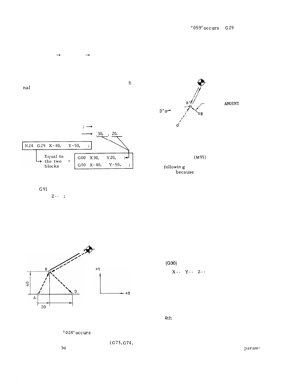
When G29 is programmed, it is not necessary to
consider the distance between point B and C in the
program. Particularly when an incremental command
is used, this is effective for returning tool to the
original position, after returning to reference zero.
Movement of C
B and of B
D is made at rapid
traverse rate simultaneously along three axes
(simultaneously four axes t) by G29. However, in an
axis for which a coordinate command was omitted,
the tool will not move.
If G28 is programmed a number of times, the
coordinates of point B which the last G28
creates is effective for the move of G29.
EXAMPLE 1 (In the case of absolute input)
Interim point
N21 G90 ;
coordinates
X
Y
z
-
N22 G28 Z1O.
Y20.
(o, 20.
, 10. )
N23 G28 X30. ;
( 30.
, 10
0
)
blocks
.
EXAMPLE 2
N31
;
N32 G28
.
N33 G28 X20.
Y40.
N34 M06 ;
N35 G29 X40.
Y-40.
c
(REFERENCE POINT)
/
40
Fig. 2.29
Notes :
. An input error
if G29 is program-
med in tool ‘radius compensation mode ( G41,
G42) or during canned cycle mode
G76, G77, G81
G89) .
An input error
if
is given
without execution of G28 after the control is
turned on.
In principle, cancel tool offset before program-
ming G28 or G29.
If they are programmed when
offset is also effective. interim positioning
point B will also be offset, and the tool passes
point B’ .
c
(REFERENCE POINT)
OFFSET
-----
/
B
(INTERIM POSITIONING
POINT)
A’
Fig. 2.30
An input error “058” occurs if G29 is given dur-
ing mirror image
.
The
command or operation must not
be taken
interim positioning point B of
G28 does not meet with that of G29.
(1) The following operations are made between
G28 and G29 commands.
Setup of coordinate system (G92, ORG key)
. Machine lock
Manual operation at Manual Absolute Off
(2) G28 and G29 are commanded in the blocks
following the block containing M94 which
cancels mirror image at the different point
from the starting point of mirror image.
(3) G28 and G29 are commanded after manual
operation at Manual Absolute Off.
2.9.17 RETURN TO 2ND, 3RD AND 4TH REFERENCE
POINT
t
G30
Pn
.
.
.
(a t...) ;
(where Pn = P2, p3, p4)
With this command, the tool first moves to an in-
terim positioning point, and then, moves to the
2nd, 3rd or 4th reference point.
P2:
2nd reference point
}
When P is omitted,
P3:
3rd reference point
the tool moves to
P4:
reference point
the 2nd reference
point.
If any axis of the coordinate instruction is omitted,
the tool remains motionless in the direction of that
axis.
Each reference point is specified by the
eters (#6612 to #6629) before hand.
35