Yaskawa J50M Instructions User Manual
Page 30
2.9.2
POSITIONING (GOO, G06) (Cent’d)
.
With the ERROR DETECT OFF mode commanded
by G06, the program advances to the next block
immediately after the completion of pulse distri-
bution.
2.9.3
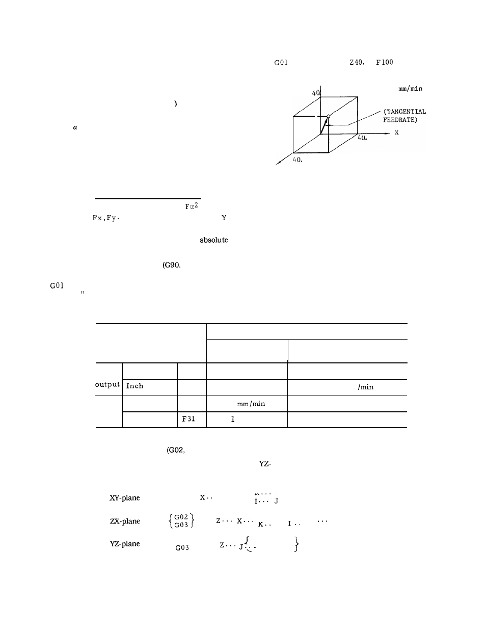
LINEAR INTERPOLATION (GOI
GO1 X.. .Y. .. Z... (a t...)
F... ;
where = A, B, C, U, V, or W
With this command, the tool is moved simultaneously in
the three (four t) axial directions resulting in a linear
motion. When a certain axis is missing in the command,
the tool does not move in the axial direction of that axis.
Feedrate is specified by an F code the feedrate in the
component axial directions are so controlled that the
resultant feedrate becomes the specified feedrate.
F
=
Fx2 + Fy2 + Fz2 +
(where
. . are feedrate in the X ,
..-
directions. )
The end point can be programmed either in
coordinates or in incremental values with G90 or G91
respectively.
( R e f e r t o 2 . 9 . 3 0 , “ A B S O L U T E
/INCREMENTAL PROGRAMMING
G9 l)”).
If no F code is given in the block containing the
or in preceding blocks, the block constitutes
an error 030. “
EXAMPLE
X 4 0 .
Y40.
;
Y
100
RESULTANT
FEEDRATE
o
z
Ftg. 2.12
Where the optional 4th axis is a rotary axis (A, B or C),
for the same F code, the feedrates in the basic three axis
directions (X, Y and Z), and the rotary axis feedrate are
as indicated.
Table 2.19 Minimum F Command Unit
In minimum F command unit
F - f u n c t i o n
Feedrate of basic
three axes
Feedrate of rotary axes
Metric
Metric input
F50
1 mm /rein
1 deg /rein
inp Ut
F31
0.1 in. /rein
2.54 deg
I n c h
Metric input
F50
1
O. 3937 deg /rein
output
Inch input
0, in. /rein
1 deg/min
N o t e :
Feedrate of linear 4th axis as the same as that of basic three axes.
2.9.4
CIRCULAR INTERPOLATION
G03)
With the following commands, the tool is controlled
plane, at a tangential speed specified by the F
along the specified circular pathes on the XV-, 2X-, or
code.
G 17
{
}
G02
{
R
G03
. Y.. .
}
F.. . ;
. . . . . .
G18
G02
{
R . . .
1
F
G03
.
.
;
G19
{
}
G02
R.. .
‘.. .
K.. .
F... ;
22