Yaskawa J50M Instructions User Manual
Page 191

c.
Procedure for storing current position data
using GOO when machine was moved from point
C to point D. Sequence No. for this data block
is NOO03.
(1) Key-in N, O, 0, 0, 3.
( 2 ) K e y - i n G , O , 0 .
(3) Depress the WR key after Y.
(4) Depress the EOB key.
( 5 ) D e p r e s s t h e I N S R T k e y .
Then, block of NOO03 GOO Y1. 000; will be stored
in the part program.
D .
Procedure of storing current position data
for three axes simultaneously when machine was
moved from point A to point D with linear inter
polation Sequence No. for the data block is
NOO04.
(1) Key-in N, O, 0, 0, 4.
( 2 ) K e y - i n G , O , 1 .
(3) Depress the WR key after X.
(4) Depress the WR key after Y.
(5) Depress the WR key after Z.
Key-in F, 1, 0, 0.
(7) Depress the EOB key.
( 8 ) D e p r e s s t h e I N S R T k e y .
Then block of NOO04 GO1 XO.700
zO.600
F1OO; will be stored in the part program.
E.
When the machine current position is at
point D (700, 1000, 600) with start at A, follow
the procedure to store the current position data
using the position data of point D when the
machine is moved from point A to point E 1200,
800, 600) .
Key-in the incremental value for each axis when
machine moves from point D to point E.
Sequence No.
for this data block is N 0005.
(1) Key-in N, O, 0, 0, 5.
(2) Key-in G, O, 1.
(3) Depress the WR key after keying-in XO. 5.
(4) Depress the WR key after keying-in Y-O. 2
(5) Depress the WR key after keying-in Z.
(6) Key-in F, 1, 0, 0.
(7) Depress the EOB key.
(8) Depress the INSRT key.
Then, block of NOO05 GO1 X1.200 YO. 800
FO. 600 F1OO: will be stored in the part program.
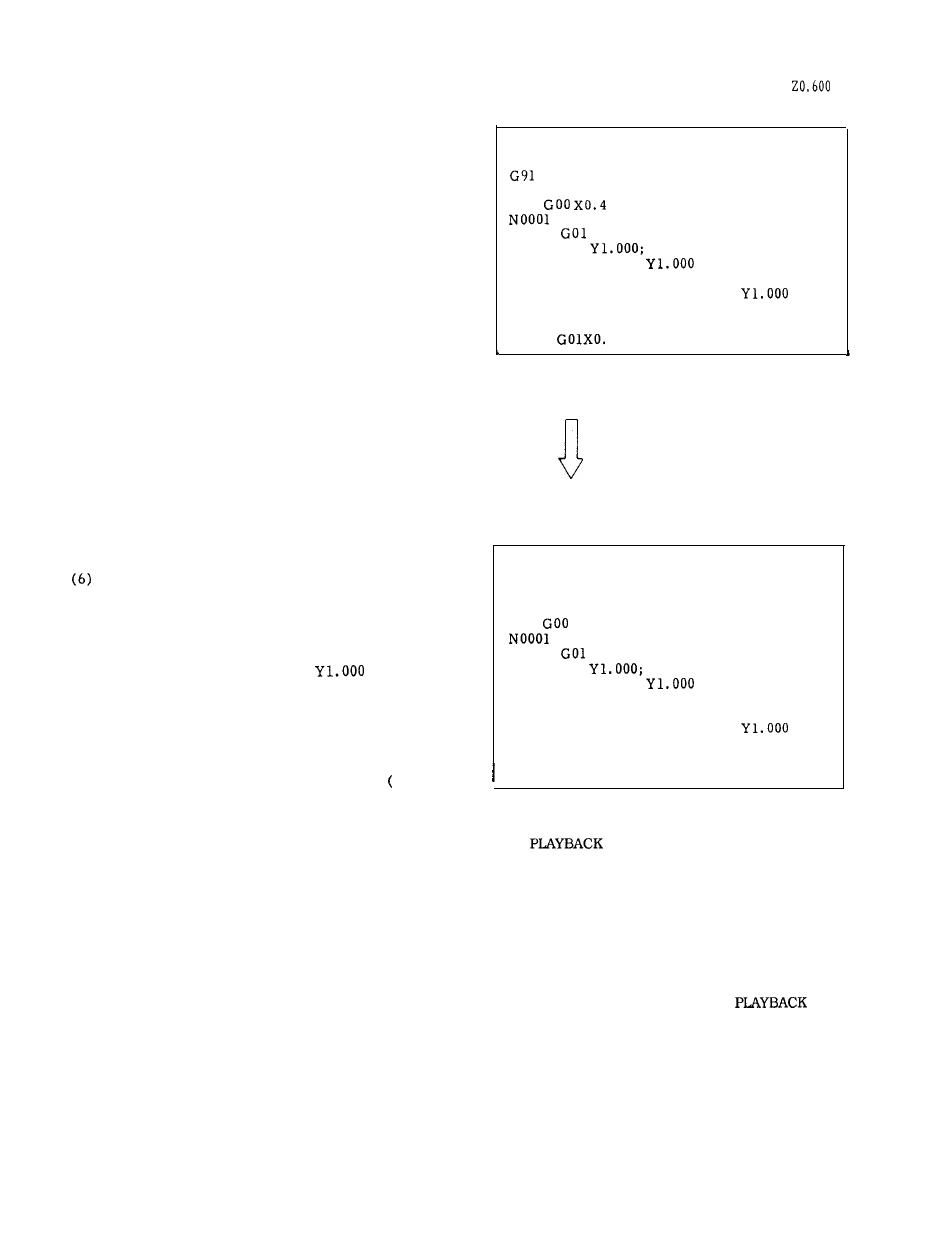
PROG (PLAYBACK)
OOO1ONOOOO
00010;
G28 XO YO ZO;
G92 X9 YO ZO;
G90
YO.2 ZO.3;
COO XO. 700;
NOO02
ZO.600 F20;
NO003 GOO
NOO04 GO1 XO. 700
ZO.600 F1OO;—
P o s
x
.700
(uNIV) z
.600
NOO05
5
RDY
Fig. 5.35
BY DEPRESSING WR KEY,
POSITION X IS ADDED TO
THE KEYED-IN VALUE.
AFTER THAT, EACH TIME
THE KEY IS DEPRESSED,
POSITION X IS INCREASED
BY
MULTIPLES (X2, X4,
X8 . ..).
P R O G ( P L A Y B A C K )
OOO1ONOOOO
00010;
G91 G28 XO YO ZO;
G92 XO YO ZO;
G90
XO.4 YO.2 ZO.3;
GOO XO. 700;
NO002
z0.600 F20;
NOO03 GOO
NOO04 GO1 XO. 700
ZO.600 F1OO;—
Pos
x
.700
(uNIV)
z
.600
NOO05 GO1 X1.200
RDY
Fig. 5.36
5.2.5.2
FUNCTION 2
In addition to the conventional playback function,
the current value of each axis, as well as the
cutting feedrate F, spindle speed S and tool
command T execution value can be written by the
external writing signal.
(1) Writing by key operation
The operation procedure is as usual. Refer to the
Operator’s manual (Par. 5.2.5.1,
function” ).
The cutting feedrate F, spindle speed S and tool
command T are also written in the same way as the
axis data.
Note that if a numeral is typed on the
keyboard before depressing the WR key, the
numeral becomes the command value.
If no numeral
is input on the keyboard after typing F or S, over-
ridden values of the current cutting feedrate
command F or spindle speed S become the command
value.
183
