Yaskawa J50M Instructions User Manual
Page 32
2.9.4 CIRCULAR INTERPOLATION (G02, G03) (Cent’d)
G17
1.. . J.. . F.. . Ln ;
With this command, complete circular interpolations
When a linear 4th axis option is used, circular
are repeated n times.
Without an L designation,
interpolation is possible in the X -, Z -, and Y -
the interpolation is executed only once.
planes in addition to the XY-, YX-, and
planes
(where = U, V, or W).
X -plane
G17
{
}
G02
{
.
}
G03
1.. .
.
;
Z -plane
G18
{
}
G02
R . . .
F
G03
K.. .
;
Y -plane
G19
G02
{
.
}
G03
.
.
;
Note :
. G17 G02
.
}
. ;
. . . . . .
Where address characters for the 4th axis is
missing as in the above command, the
plane
is automatically selected. Circular interpolation
cannot be performed on the axes including
rotary 4th axis.
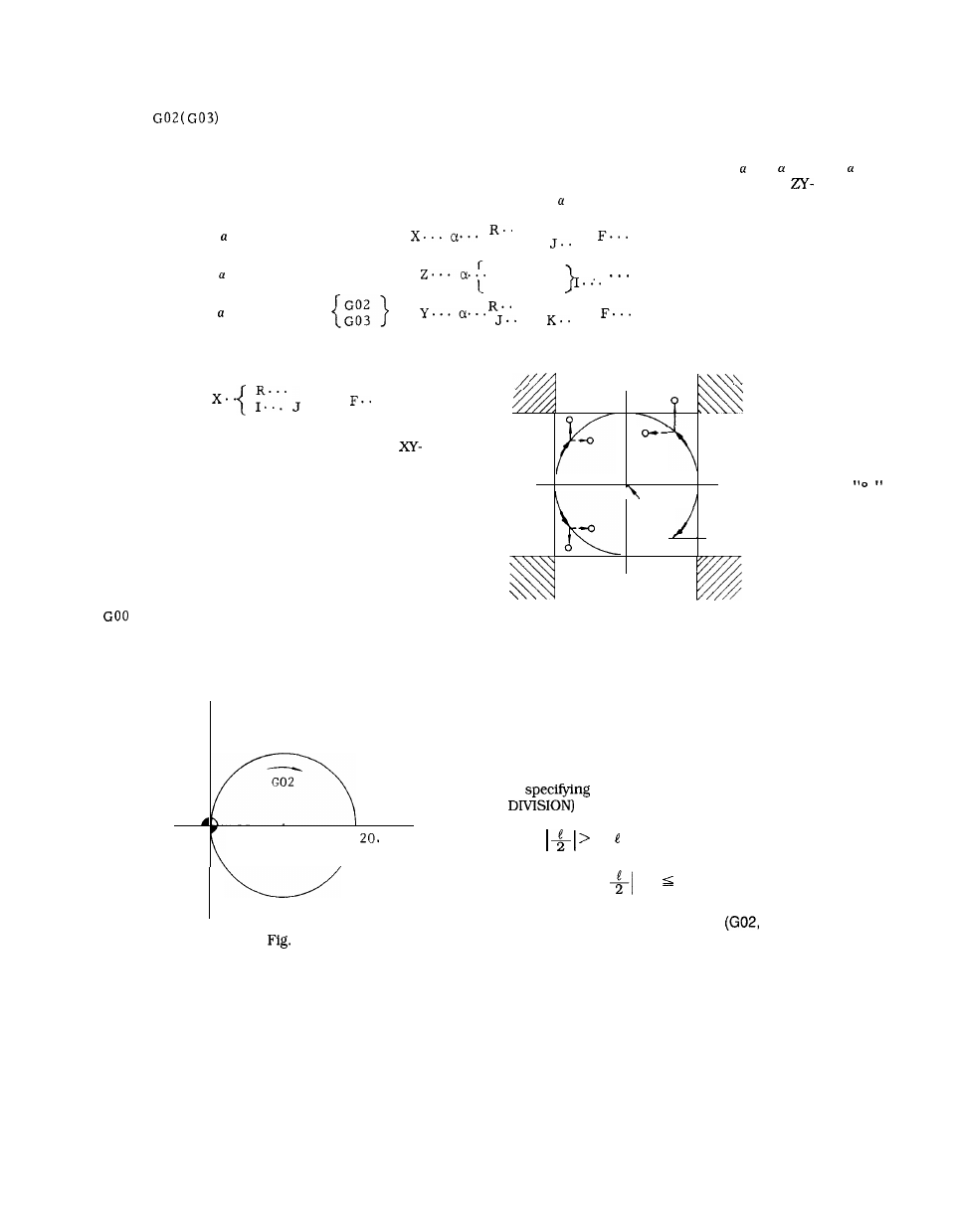
Circular pathes covering two or more quadrants
can be programmed in a single block. A com-
plete closed circle can also be programmed.
EXAMPLE
XO YO ;
G02 XO YO 110. JO F1OO ;
. . .
complete circle
Y
x
10.
2.16
When the coordinate values of the end point of a circular
path is not exactly on the correct circular path due to
calculation errors, etc., correction is made as shown below.
Points O are commanded as end point. (See Fig. 2.17).
The end point i
represented by
CENTER
* -
0
\
\\
/
Fig. 2.17
.s
.
When the end point is programmed in the hatch-
ed areas shown above, no alarm state is creat-
ed, but the tool will keep on rotating.
Especially when tool compensation is applied,
coordinate values of the point and the center
must be programmed accurately.
When radius is specified as O (I, J = O on G17 plane)
in
circular arc, alarm 102 (CAL ERROR =
is triggered.
When
R ( : distance from the start point to the
end point) at R command, the error is compensated for
in the range of
– R #6649.
2.9.5 HELlCAL INTERPOLATION
G03)
t
A circular interpolation on a certain plane, and
a linear interpolation along an axis not included
in that plane can be executed in synchroniza-
tion, and this combined interpolation is called
helical interpolation.
24